Operating mechanism for a parking brake

a technology of operating mechanism and parking brake, which is applied in the direction of brake action initiation, braking system, dynamo-electric machines, etc., can solve the problems of high manufacturing effort, high maintenance effort, and complex structure of actuator and driv

Inactive Publication Date: 2006-02-02
FICO CABLES
View PDF7 Cites 1 Cited by
  • Summary
  • Abstract
  • Description
  • Claims
  • Application Information

AI Technical Summary

Benefits of technology

[0009] The above problem is solved by an operating mechanism for a parking brake, particularly for motor vehicles, which is arranged in a housing. This operating mechanism comprises a threaded rod driven by a motor having a first brake cable fixing guided on said threaded rod for the transformation of the rotation of said motor in a linear movement of said brake cable fixing and a second brake cable fixing in axial arrangement with said first brake cable fixing and said motor for performing a relative movement of said first and said second brake cable fixing to each other wherein said first and said second brake cable fixing can execute a common relative movement in view of said housing for a uniform load distribution to the connected brake cables.

Problems solved by technology

The downstream assembly for the force distribution requires on the one hand high manufacturing efforts and on the other hand high maintenance efforts.
The actuator as well as its drive consists of multi part expensive constructions.
The rotation of the electric motor is transmitted to the actuator via a constructively expensive set of gears.
The plurality of the parts necessary therefore occupy a lot of space, have a high weight and require efforts in manufacturing and maintenance.
Furthermore, said actuator consists of a multi part construction with low tolerances which also require high efforts in manufacturing and maintenance.

Method used


Image

  • Operating mechanism for a parking brake
  • Operating mechanism for a parking brake
  • Operating mechanism for a parking brake

Examples


Embodiment Construction

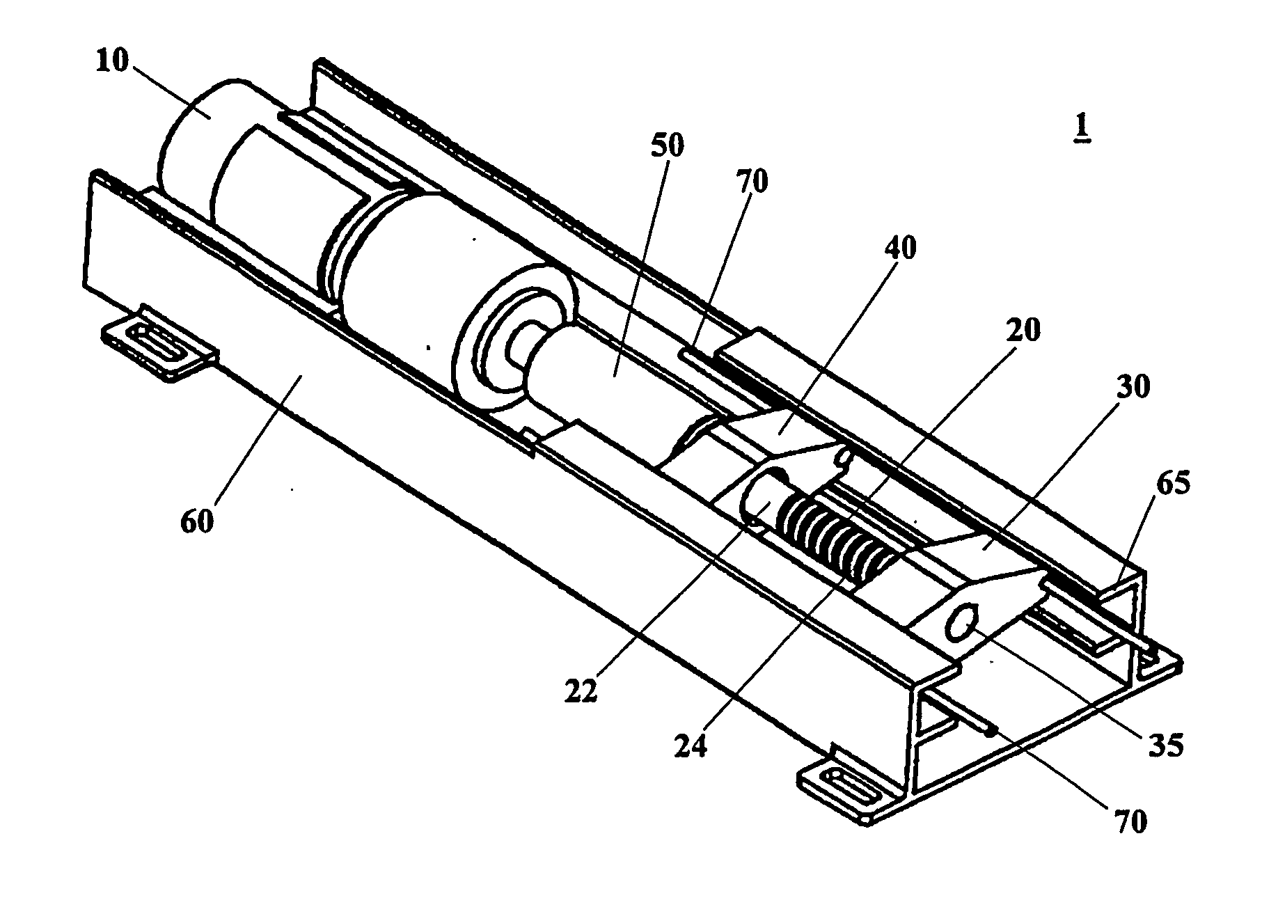
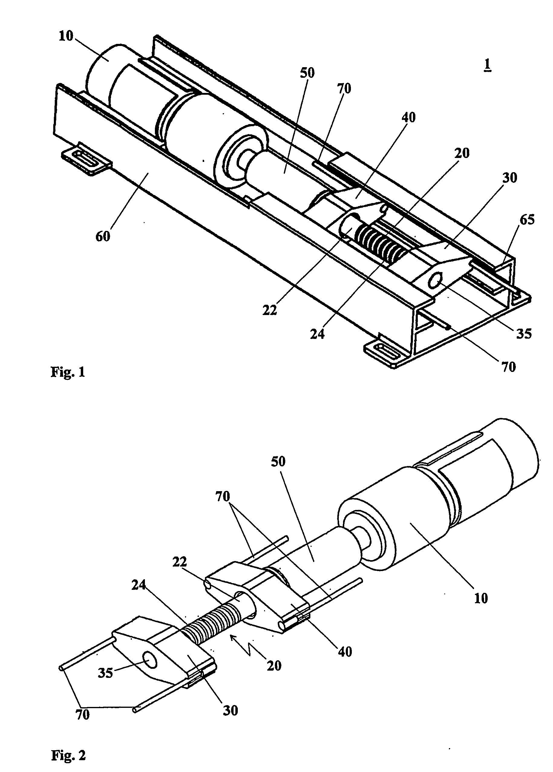
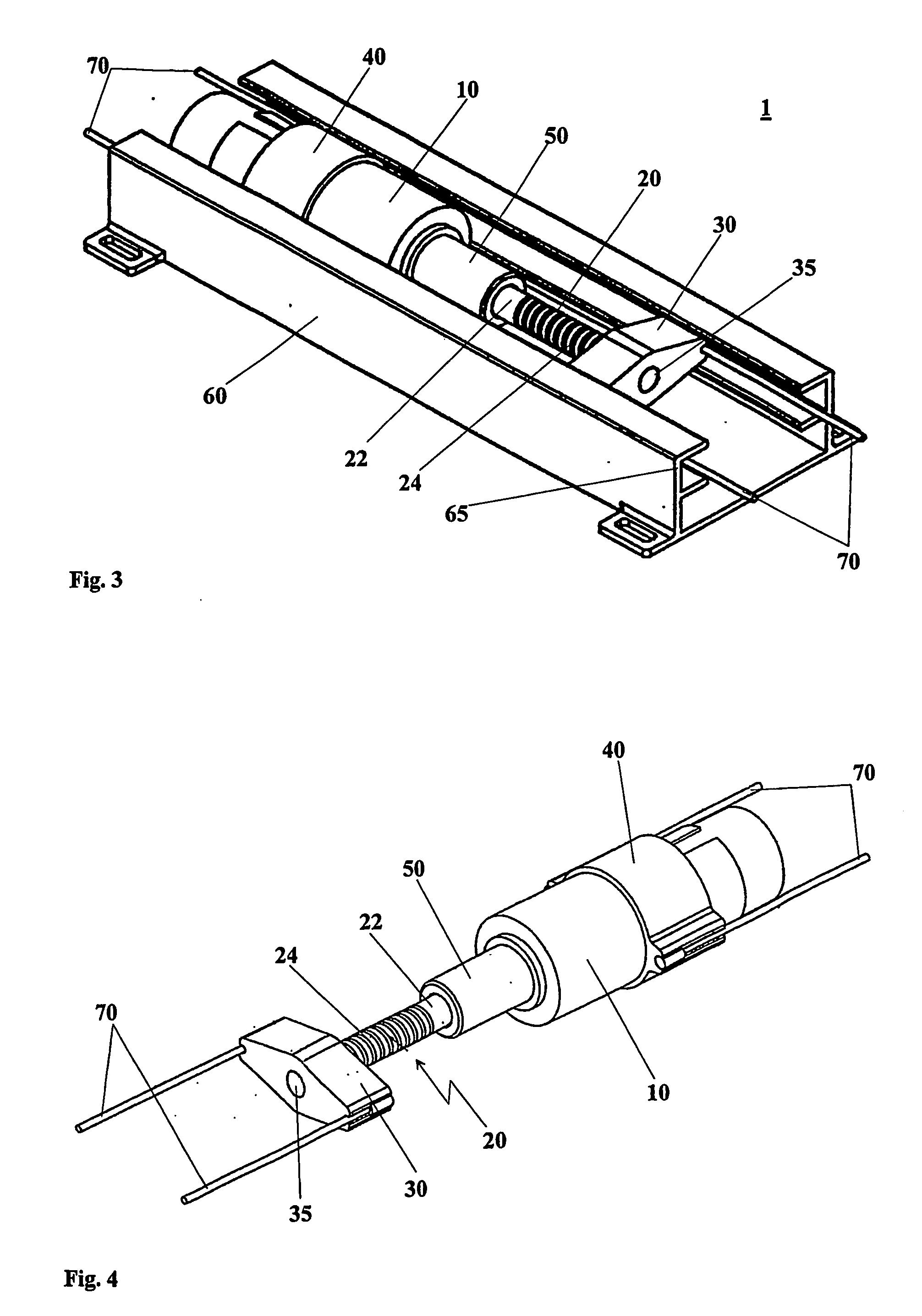
[0032] A first preferred embodiment of the operating mechanism 1 for a parking brake according to the invention is shown in a perspective general view in FIG. 1. Preferably according to the invention, the operating mechanism 1 is accommodated in a housing 60. Said operating mechanism 1 is comprised of a motor 10 which drives a threaded rod 20. Said motor 10 is preferably according to the invention an electric motor wherein its function can be also carried out by other suitable drives.

[0033] Said motor 10 rigidly installed in said housing 60 according to a preferred embodiment of the present invention is preferably according to the invention connected to the threaded rod 20 via a coupling element 50. Said coupling element 50 provides a positive connection between said motor 10 and said threaded rod 20 which realizes a transmission of the motor rotation to the threaded rod 20 and which at the same time allows an axial displacement of said threaded rod 20 in its axial direction within...


PUM


Abstract

An operating mechanism (1) for a parking brake, particularly for motor vehicles, arranged in a housing (60) comprising a threaded rod (20) driven by a motor (10) having a first brake cable fixing (30) guided on said threaded rod (20) for the transformation of said rotation of said motor (10) in a linear movement of said first brake cable fixing (30); and a second brake cable fixing (40) in axial arrangement with said first brake cable fixing (30) and said motor (10) for executing a relative movement of said first (30) and said second brake cable fixing (40) to each other whereby said first (30) and said second brake cable fixing (40) can carry out a common relative movement with respect to the housing (60) for a uniform load distribution to the connected brake cables (70).

Description

TECHNICAL FIELD OF THE INVENTION [0001] The present invention relates to an operating mechanism for a parking brake, particularly for a parking brake in motor vehicles. PRIOR ART [0002] Different operating mechanisms for parking brakes are known in the prior art. The simplest technical solution consists of a lever mechanism arranged in the vehicle compartment. This lever mechanism is for example manually operated by the driver so that the brake cables leading to the brakes are tightened or released. In this manner, the connected brakes are operated. Mostly, this operating mechanism is connected to a further downstream lever mechanism which uniformly distributes the applied mechanical loads to the connected brake cables and brakes. [0003] Further operating mechanisms for parking brakes comprise a drive by means of which via an actuator the connected brake cables are operated. For example an electric motor connected via a set of gears with a spindle is such a drive. At least one brake...

Claims


Application Information

Patent Timeline
Patent Type & Authority Applications(United States)
IPC IPC(8): F16D65/14F16D65/28B60T7/04B60T7/10B60T11/04B60T11/06H02K7/106H02K7/116
CPCB60T7/042B60T11/06B60T11/046B60T7/107
Inventor TERRADAS, JAUME PRATJORNET, JORDI V.AGRATMUNT, ISMAEL C.FLOREZ, JESUS A.
Owner FICO CABLES
Why Eureka
Try Eureka