
System and method for controlling an outdoor air conditioner

a technology for outdoor air conditioners and systems, applied in domestic cooling devices, lighting and heating devices, heating types, etc., can solve the problems of air conditioning load, waste of energy, and increase the temperature of the room

Active Publication Date: 2016-05-26
MITSUBISHI ELECTRIC CORP
View PDF9 Cites 16 Cited by
  • Summary
  • Abstract
  • Description
  • Claims
  • Application Information

AI Technical Summary

Benefits of technology

The patent describes an air conditioning system for buildings that uses an outdoor air conditioner to cool the air, and indoor air conditioners to heat or cool the air for individual spaces. The system includes a control circuit that adjusts the supply air temperature based on the desired temperatures and the air conditioning load in each space. The control circuit can adjust the supply air temperature to match the desired temperatures or to an average of the desired temperatures. The system can also use sensors to determine the air conditioning load, and can adjust the supply air temperature accordingly. The technical effect of this system is to provide efficient and precise air conditioning for individual spaces, while minimizing energy consumption and improving comfort for the occupants.

Problems solved by technology

However, the individual rooms can often have an air conditioning load associated with them.
For example, if a room is full of people, that will tend to raise the temperature in that room.
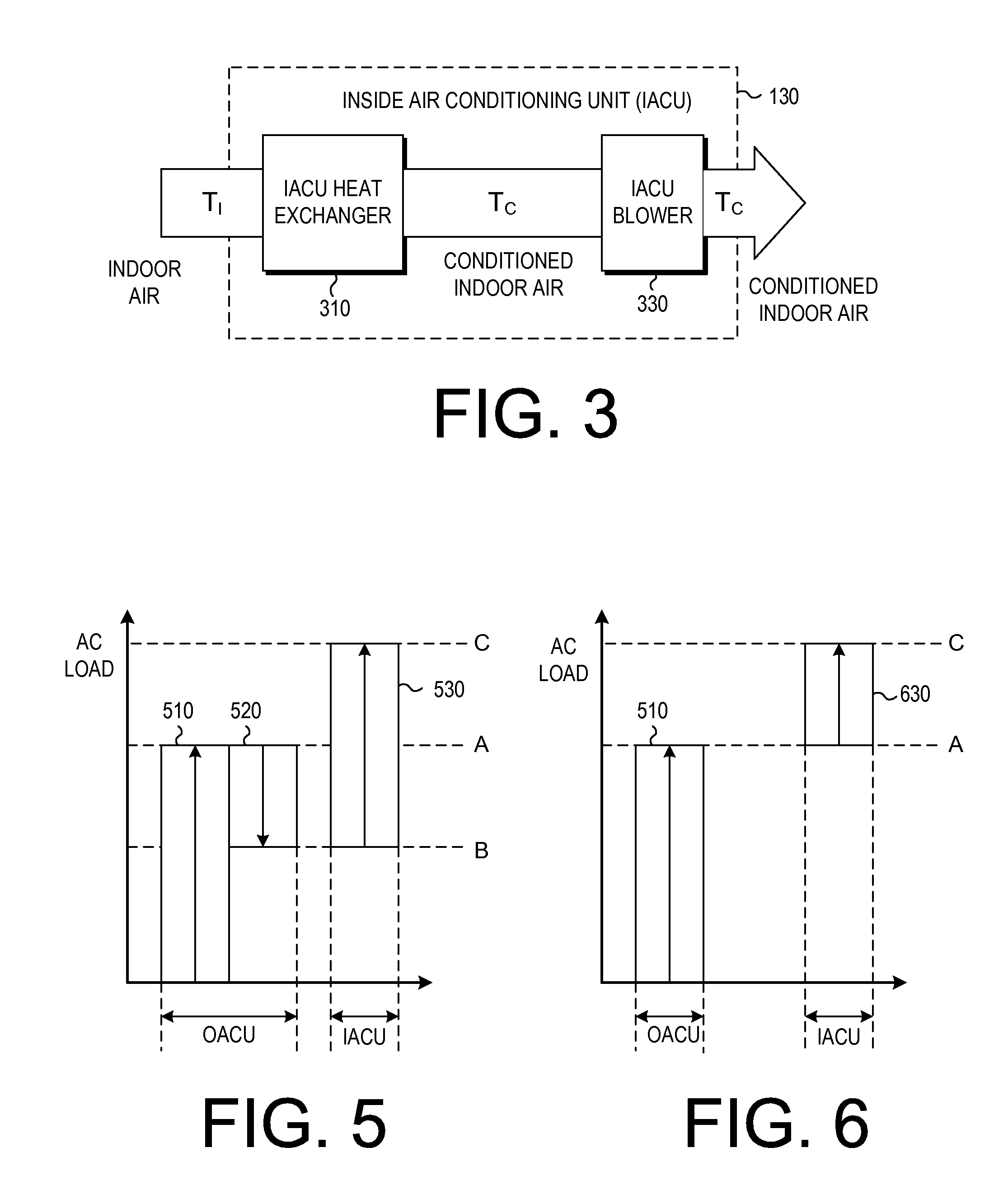
In situations in which the air is dehumidified and the air conditioning load in a room requires an IACU to cool the air, this may result in the OACU heating the air, while one or more IACUs cool the air.
This is a waste of energy, since the OACU and the IACU are working at cross purposes.

Method used


Image

  • System and method for controlling an outdoor air conditioner
  • System and method for controlling an outdoor air conditioner
  • System and method for controlling an outdoor air conditioner

Examples


Embodiment Construction

[0039]The instant disclosure is provided to further explain in an enabling fashion the best modes of performing one or more embodiments of the present invention. The disclosure is further offered to enhance an understanding and appreciation for the inventive principles and advantages thereof, rather than to limit in any manner the invention. The invention is defined solely by the appended claims including any amendments made during the pendency of this application and all equivalents of those claims as issued.

[0040]It is further understood that the use of relational terms such as first and second, and the like, if any, are used solely to distinguish one from another entity, item, or action without necessarily requiring or implying any actual such relationship or order between such entities, items or actions. Likewise, the use of positional terms such as front, back, side, top, and bottom are used solely to provide a reference point for one particular orientation, and to enhance clar...


PUM


Abstract

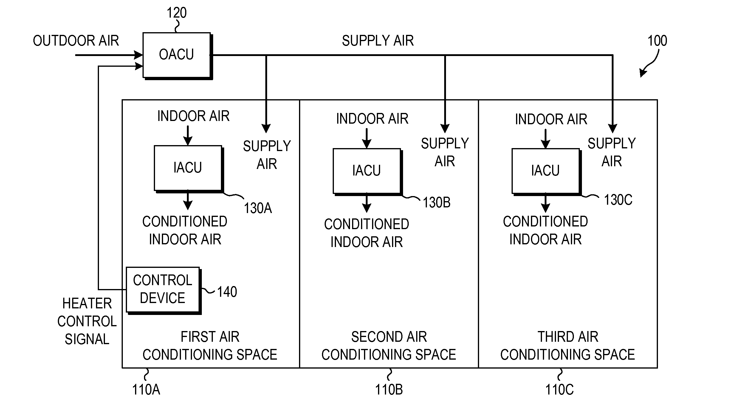
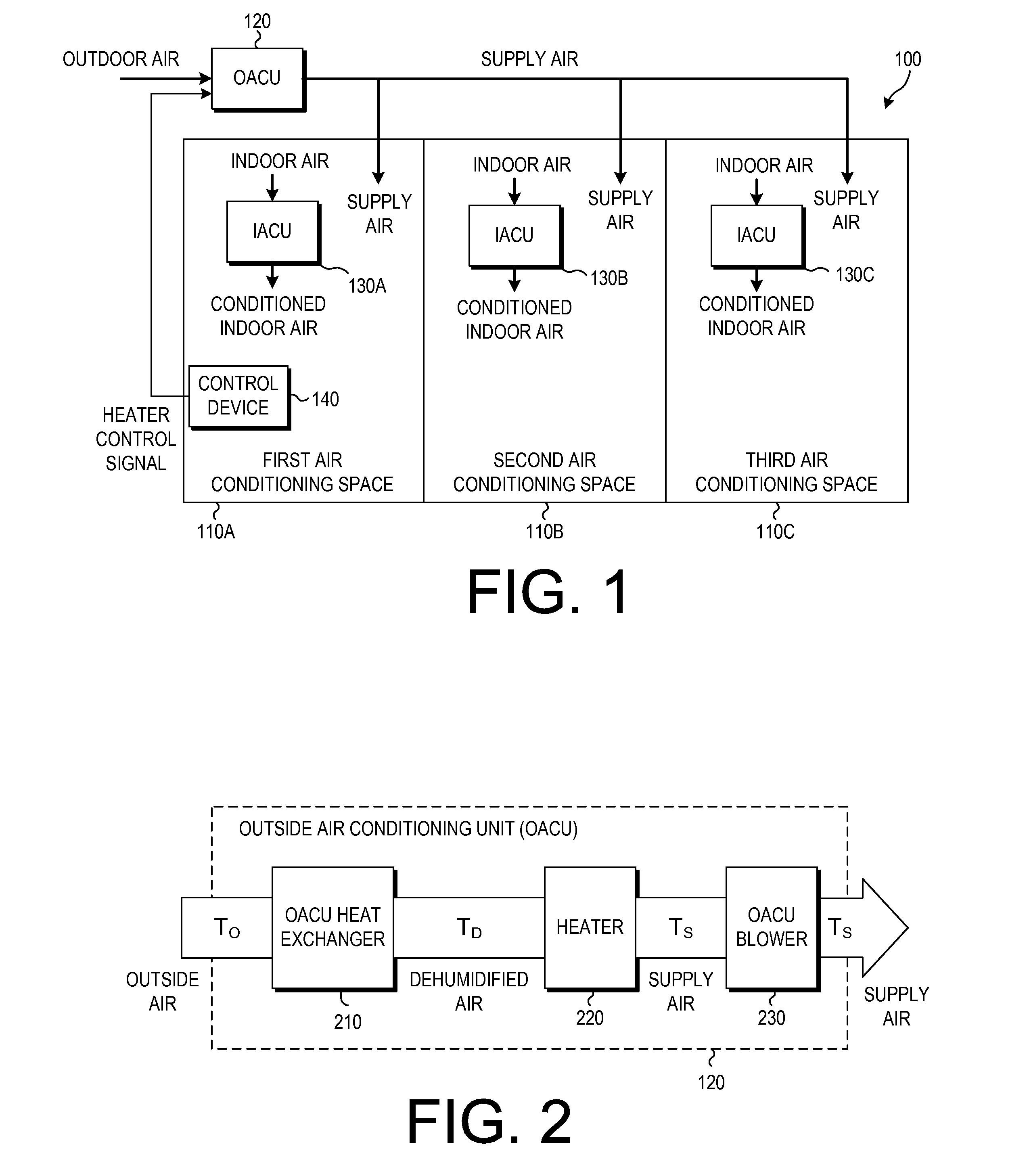
An air conditioning system is provided, including: an outdoor air conditioner, configured to cool outdoor air at an outdoor temperature into dehumidified air at a dehumidified temperature, to heat the dehumidified air into supply air at a supply air temperature, and to provide the supply air to a plurality of rooms; a plurality of indoor air conditioners provided inside the plurality of rooms, respectively, each indoor air conditioner being configured to draw in input air at an input temperature, to heat or cool the input air into output air at an output temperature, and to provide the output air to a corresponding room; a control circuit configured to determine whether an air conditioning load exists in a set number of the plurality of rooms, and to adjust operation of the outdoor air conditioner to set the supply air temperature based on whether the air conditioning load is determined to exist.

Description

FIELD OF THE INVENTION[0001]The present invention relates generally to air conditioning systems that include an outside air conditioning unit and one or more indoor air conditioning units. More particularly, the present invention relates to a system and method for controlling the degree to which air is heated by an outdoor air conditioning unit in such a system.BACKGROUND OF THE INVENTION[0002]In many conventional air-conditioning systems, the system includes an outdoor air conditioning unit (OACU) and one or more indoor air conditioning units (IACUs) in one or more rooms of a structure, respectively. The outdoor air conditioning unit provides supply air at a base temperature, while the individual IACUs refine the temperature of the air in the individual rooms to achieve a desired air temperature.[0003]In addition to heating and cooling air, many air conditioning systems also operate to remove humidity from the air they provide. This is generally done by cooling the outdoor air down...

Claims


Application Information

Patent Timeline
Patent Type & Authority Applications(United States)
IPC IPC(8): F24F3/153F24F11/00
CPCF24F11/0079F24F3/153F24F11/30F24F2110/10F24F2110/12F24F2120/10F24F2140/60F24F2130/20F24F11/62F24F11/77Y02B30/70F24F11/46F24F11/63
Inventor ITO, SHINICHINOMOTO, SOSAKAI, DAISUKE
Owner MITSUBISHI ELECTRIC CORP
Learn More