Novel air conditioning system in machine room based on underfloor air distribution and air distribution method thereof

A computer room air conditioner, a new type of technology, applied in the heating method, space heating and ventilation details, cooling/ventilation/heating renovation, etc., which can solve the problems of different cooling effects of the cabinets, insufficient use of air supply for cooling, and discounts on operating efficiency. , to achieve the effect of reducing air supply, improving efficiency and improving energy efficiency ratio

Inactive Publication Date: 2013-02-27
东南大学常州研究院
View PDF4 Cites 3 Cited by
  • Summary
  • Abstract
  • Description
  • Claims
  • Application Information

AI Technical Summary

Problems solved by technology

In this process, due to the temperature stratification of the room, the temperature in the upper space of the cabinet is higher and the temperature in the lower space is lower, resulting in different cooling effects on each layer of the cabinet.
At the same time, because only part of the cold air enters the cabinet to cool the computer equipment, most of the supply air is mixed with the exhaust air of the cabinet and then discharged out of the room. The supply air is not fully utilized to cool the cabinet, and the operating efficiency is greatly reduced.

Method used


Image

  • Novel air conditioning system in machine room based on underfloor air distribution and air distribution method thereof
  • Novel air conditioning system in machine room based on underfloor air distribution and air distribution method thereof
  • Novel air conditioning system in machine room based on underfloor air distribution and air distribution method thereof

Examples


Embodiment Construction

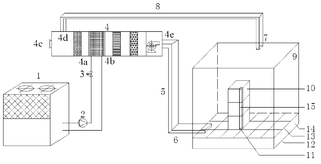
[0023] combined with figure 1 - attached Figure 4 Further explain the specific embodiment of the present invention: the cold / hot water output end of the air source cold / hot water unit 1 is connected to the input end of the water pump 2, the output end of the water pump 2 is connected to the input end of the electric valve 3, and the output end of the electric valve 3 is connected to the air conditioner The first input end 4a of the box 4 and the first output end 4b of the air conditioning box 4 are connected to the input end of the air source cold / hot water unit 1 . The second output end 4e of the air-conditioning box 4 is connected to the air input end 6 of the room 9 through the first pipeline 5, and the air output end 7 of the room 9 is connected to the second input end 4d of the air-conditioning box through the second pipeline 8. The third input end 4c of the air-conditioning box communicates with the atmosphere. The internal air supply cabinet 10 is placed on the elev...


PUM


Abstract

The invention relates to a novel air conditioning system in a machine room based on underfloor air distribution and an air distribution method thereof. A cold / hot water output end of an air source cold / hot water unit is connected with the input end of a water pump. The input end of the water pump is connected with the input end of an electrically operated valve. The output end of the electrically operated valve is connected with the first input end of an air handling unit, and the first output end of the air handling unit is connected with the input end of the air source cold / hot water unit. The second output end of the air handling unit is connected with the air input end of the room through a first pipeline. The air output end of the room is connected with the second input end of the air handling unit through a second pipeline. The third input end of the air handling unit is communicated with atmosphere. An inner air distribution cabinet is placed on an elevated floor. An air distribution opening of an air distribution channel of the inner air distribution cabinet is connected with an air distribution opening of the elevated floor. According to the system, air is directly distributed to nearby computers in layers of the air distribution cabinet, so that high air distribution temperature is allowed, thereby further improving the water supply temperature of the air source cold / hot water unit, improving the energy efficiency ratio and saving the energy source.

Description

technical field [0001] The invention relates to a novel machine room air-conditioning system based on floor air supply and an air supply method thereof, belonging to the technical field of refrigeration and air-conditioning system design and manufacture. Background technique [0002] With the rapid development of computer technology and information network, almost all large enterprises and institutions have their own computer rooms for placing various servers, routers and other equipment, and they are in long-term uninterrupted operation. In this way, higher requirements are put forward for the temperature and humidity of the computer room, the layout of cables and communication lines. [0003] The floor air supply air conditioning system uses the space between the elevated floor and the floor as the air supply static plenum, and the ample space of the static plenum can be used as the channel for cables and communication lines. Moreover, the floor air supply system has the ...

Claims


Application Information

Patent Timeline
Patent Type & Authority Applications(China)
IPC IPC(8): H05K7/20F24F13/068
Inventor 张恺张小松李舒宏
Owner 东南大学常州研究院
Why Eureka
Try Eureka