Mechanism for attachment of accessories to gun

Inactive Publication Date: 2016-05-26
LEY RYAN M
View PDF1 Cites 7 Cited by
  • Summary
  • Abstract
  • Description
  • Claims
  • Application Information

AI Technical Summary

Benefits of technology

The present invention is a cheap and durable mechanism that allows for the attachment of various accessories to a gun with parallel upper rails and a groove on the bottom of the frame. It uses a rigid track with parallel channels and a retractable protrusion that fits into the groove on the bottom of the frame. This mechanism helps stabilize the attachment accessory in three directions: vertical, horizontal, and longitudinal. This is achieved without needing delicate clips or button releases, and instead uses a sturdy design including the parallel channels and retractable protrusion.

Problems solved by technology

However, the present state of the art is such that these mechanisms frequently comprise delicate and finely calibrated clips, button releases, and the like.
Though admittedly functional for the purpose of facilitating the attachment of an accessory to the barrel of a gun, delicate and finely calibrated components in the attachment mechanisms known in the art are undesirable from a manufacturing cost perspective and they further leave the user with a product that is not durable and, therefore, not well-suited for high intensity activities undertaken while the mechanism is engaged, including without limitation, tactical training exercises utilizing a gun.

Method used


Image

  • Mechanism for attachment of accessories to gun
  • Mechanism for attachment of accessories to gun
  • Mechanism for attachment of accessories to gun

Examples


Embodiment Construction

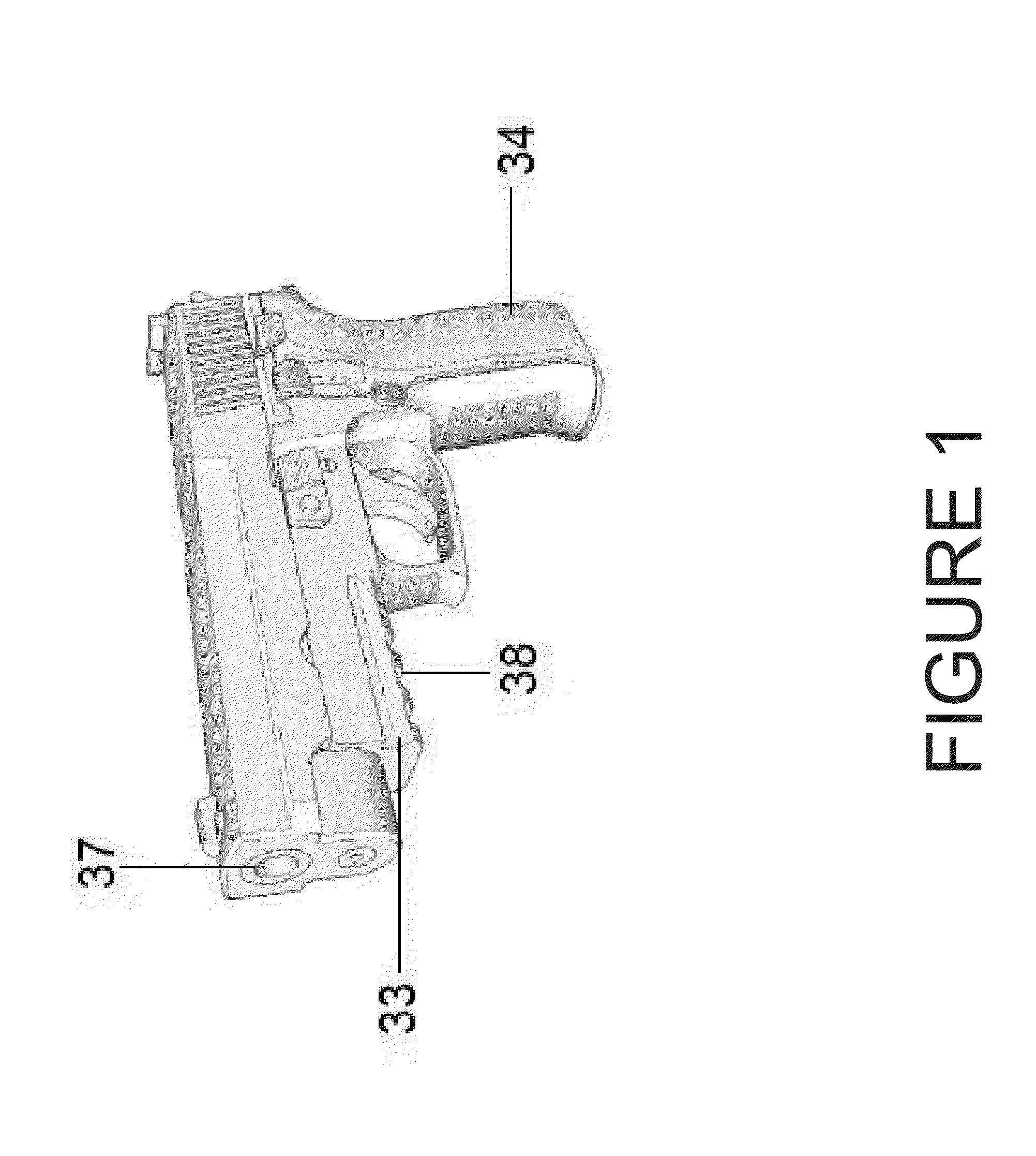
[0018]Referring now to the invention in more detail, in FIG. 1 there is shown an example of a handgun of a type that would be compatible for use with the now disclosed inventive mechanism. Specifically depicted is a handgun having a handle 34 and barrel 37, and also having a pair of parallel lateral rails 33 at the bottom of the barrel 37 frame and at least one groove 38 perpendicular to and between the parallel lateral rails 33, the groove 38 also being at the bottom of the barrel 37 frame. It is the presence of these parallel lateral rails 33 and the perpendicular groove 38 that is necessary for a weapon to be compatible with the now disclosed inventive mechanism.

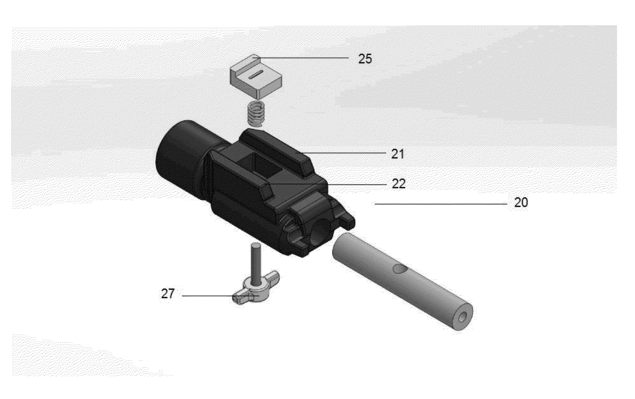
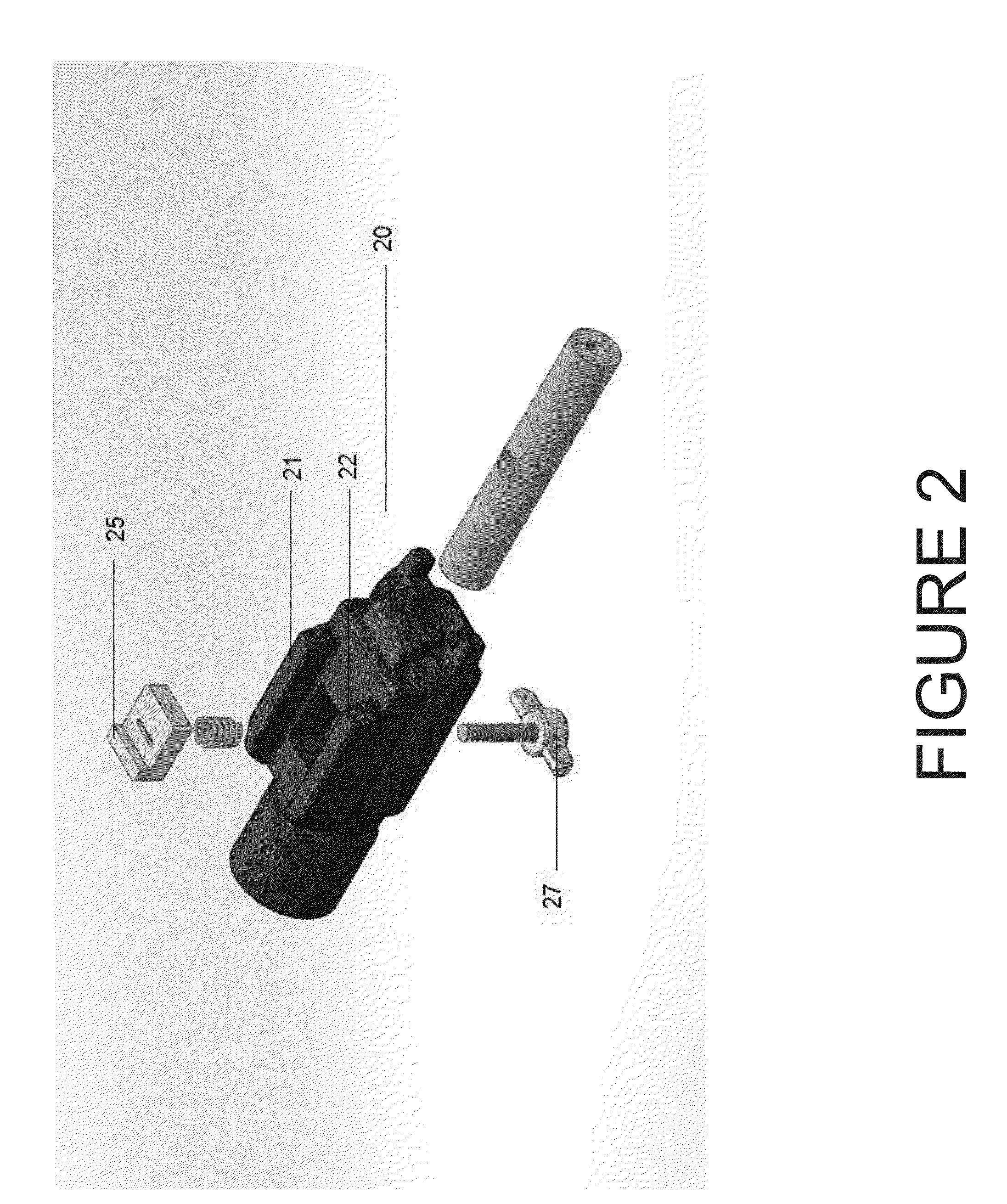
[0019]Further referring to the invention in more detail, in FIG. 2 there is shown an exploded view of an arbitrary widget 20 making use of the now disclosed inventive mechanism in association with a compatible handgun. FIG. 2 illustrates a first lateral channel 21 engaging a first parallel lateral rail 33 (not shown) of t...


PUM


Abstract

A system for attaching and stabilizing a gun attachment accessory to the frame of a firearm in which the firearm frame has two parallel lateral rails running longitudinally along the length of the firearm frame and a one groove in the bottom of the firearm barrel frame positioned between and perpendicular to the lateral rails. A gun attachment accessory mounted to the frame via the lateral rails features a protrusion located on the upper surface of an accessory that is equipped with means to extend the protrusion such that it engages with the groove in the bottom of the firearm frame. The means to extend the protrusion such that it engages with the groove include a thumb screw possibly equipped with a compression spring, threaded through a bore such that the turning of the screw raises or lowers a platform featuring the protrusion.

Description

CROSS-REFERENCE TO RELATED APPLICATIONS[0001]This application claims the benefit of priority to U.S. Provisional Application Number 62 / 083,216 filed on Nov. 22, 2014. The content of United States Provisional Application Number 62 / 083,216 filed on Nov. 22, 2014 is incorporated by reference herein in its entirety.STATEMENT REGARDING FEDERALLY SPONSORED RESEARCH OR DEVELOPMENT[0002]Not Applicable.THE NAMES OF THE PARTIES TO A JOINT RESEARCH AGREEMENT[0003]Not Applicable.INCORPORATION-BY-REFERENCE OF MATERIAL SUBMITTED ON A COMPACT DISC[0004]Not Applicable.BACKGROUND OF THE INVENTION[0005](a) Field of the Invention.[0006]The present invention is in the technical field of accessories that may be attached to guns. More particularly, the present invention is in the technical field of mechanisms that provide for the attachment of accessories to guns.[0007](b) Background Art.[0008]The technical field of the present invention has long known of a variety of mechanisms providing for the attachm...

Claims


Application Information

Patent Timeline
IPC IPC(8): F41C27/00
CPCF41C27/00F41G11/003
Inventor LEY, RYAN M.
Owner LEY RYAN M
Why Eureka
Try Eureka