LED ring light and manufacture method of LED ring light and image measuring device and optical device using LED ring light

Inactive Publication Date: 2016-05-26
MITUTOYO CORP
View PDF5 Cites 7 Cited by
  • Summary
  • Abstract
  • Description
  • Claims
  • Application Information

AI Technical Summary

Benefits of technology

The present invention is an LED ring light and its manufacturing method that improves yield and image measuring devices and optical devices using the LED ring light. The invention uses multiple substrates arranged with LEDs to avoid defective individual substrates from being wasted. This improves the yield rate of the LED ring light.

Problems solved by technology

“Generally the same” used here means that the shapes are exactly or almost the same as a result of manufacturing based on the same standards and designs and a margin of error in manufacturing is to be allowed.

Method used


Image

  • LED ring light and manufacture method of LED ring light and image measuring device and optical device using LED ring light
  • LED ring light and manufacture method of LED ring light and image measuring device and optical device using LED ring light
  • LED ring light and manufacture method of LED ring light and image measuring device and optical device using LED ring light

Examples


Embodiment Construction

[0030]The particulars shown herein are by way of example and for purposes of illustrative discussion of the embodiments of the present invention only and are presented in the cause of providing what is believed to be the most useful and readily understood description of the principles and conceptual aspects of the present invention. In this regard, no attempt is made to show structural details of the present invention in more detail than is necessary for the fundamental understanding of the present invention, the description taken with the drawings making apparent to those skilled in the art how the forms of the present invention may be embodied in practice.

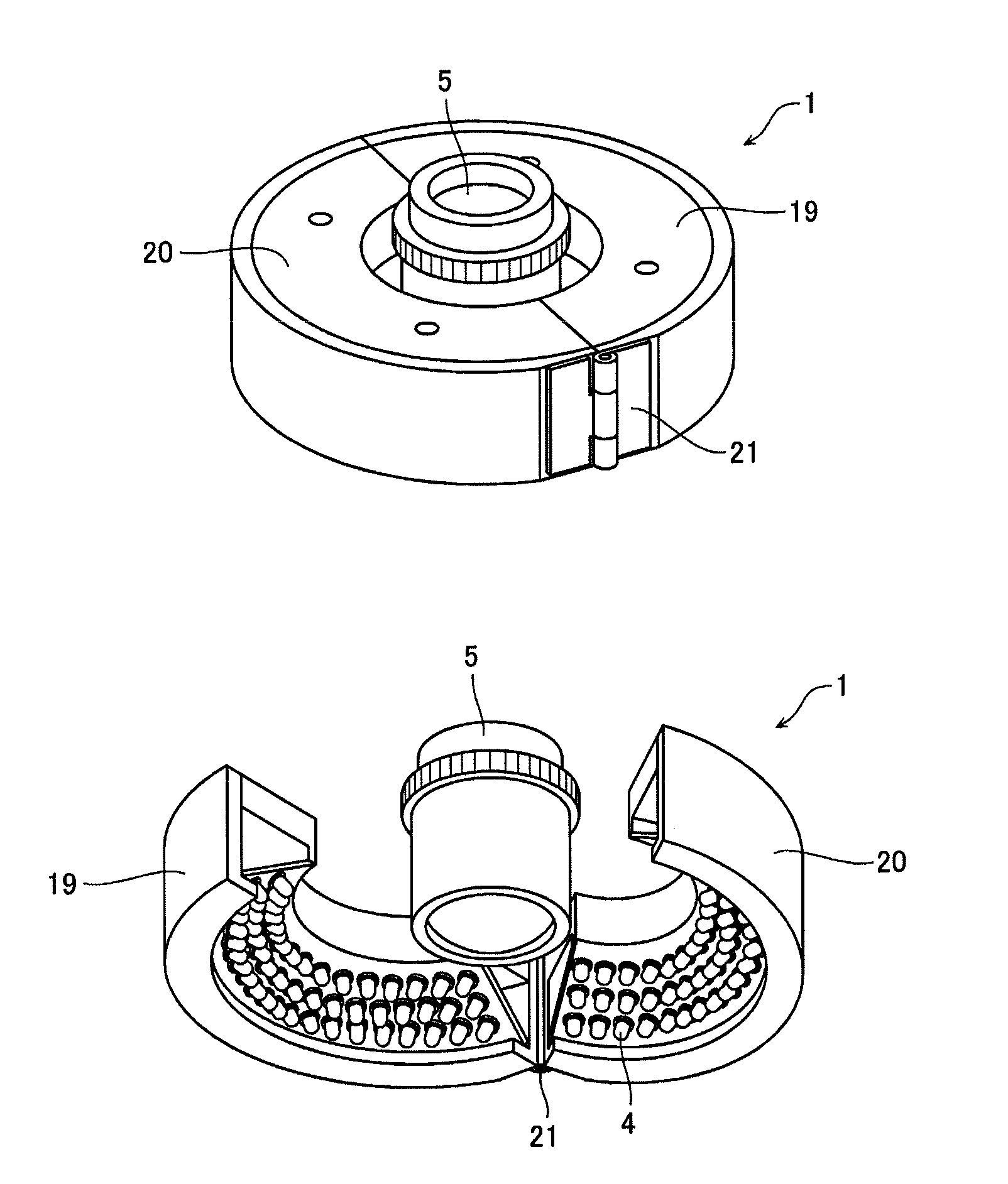
[0031]Below is a detailed explanation of favorable embodiments of the present invention with reference to the drawings. An LED ring light according to a first embodiment of the present invention is common to the LED ring light shown in FIG. 1 in an aspect where a substrate arranged with LEDs is held inside a generally annular hol...


PUM

PropertyMeasurementUnit
Flexibilityaaaaaaaaaa
Shapeaaaaaaaaaa

Abstract

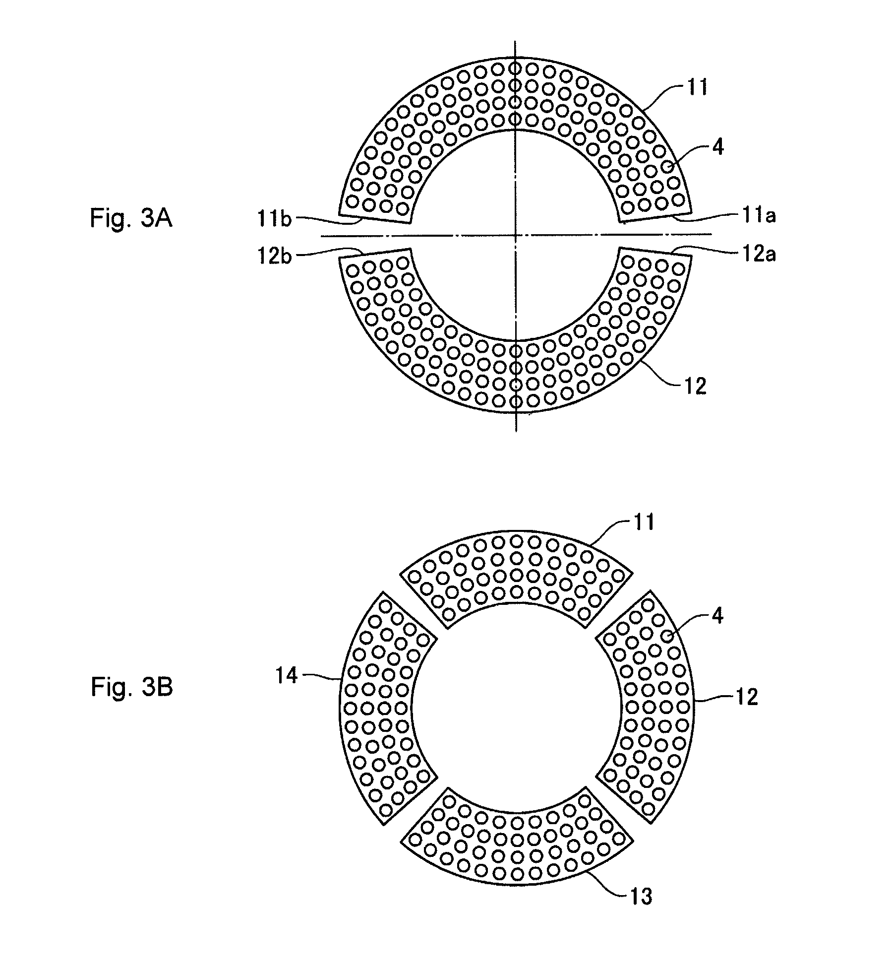
An LED ring light including a holding frame having a generally annular shape in a plan view and an aperture into which an objective lens can be inserted around a center of the holding frame; an LED substrate held inside the holding frame in a generally frusto-conical shape; and a plurality of LEDs arranged on an inner circumferential surface of the LED substrate. The LED substrate is divided at a plurality of locations in a circumferential direction of the inner circumferential surface of the holding frame by arranging a plurality of substrates side by side.

Description

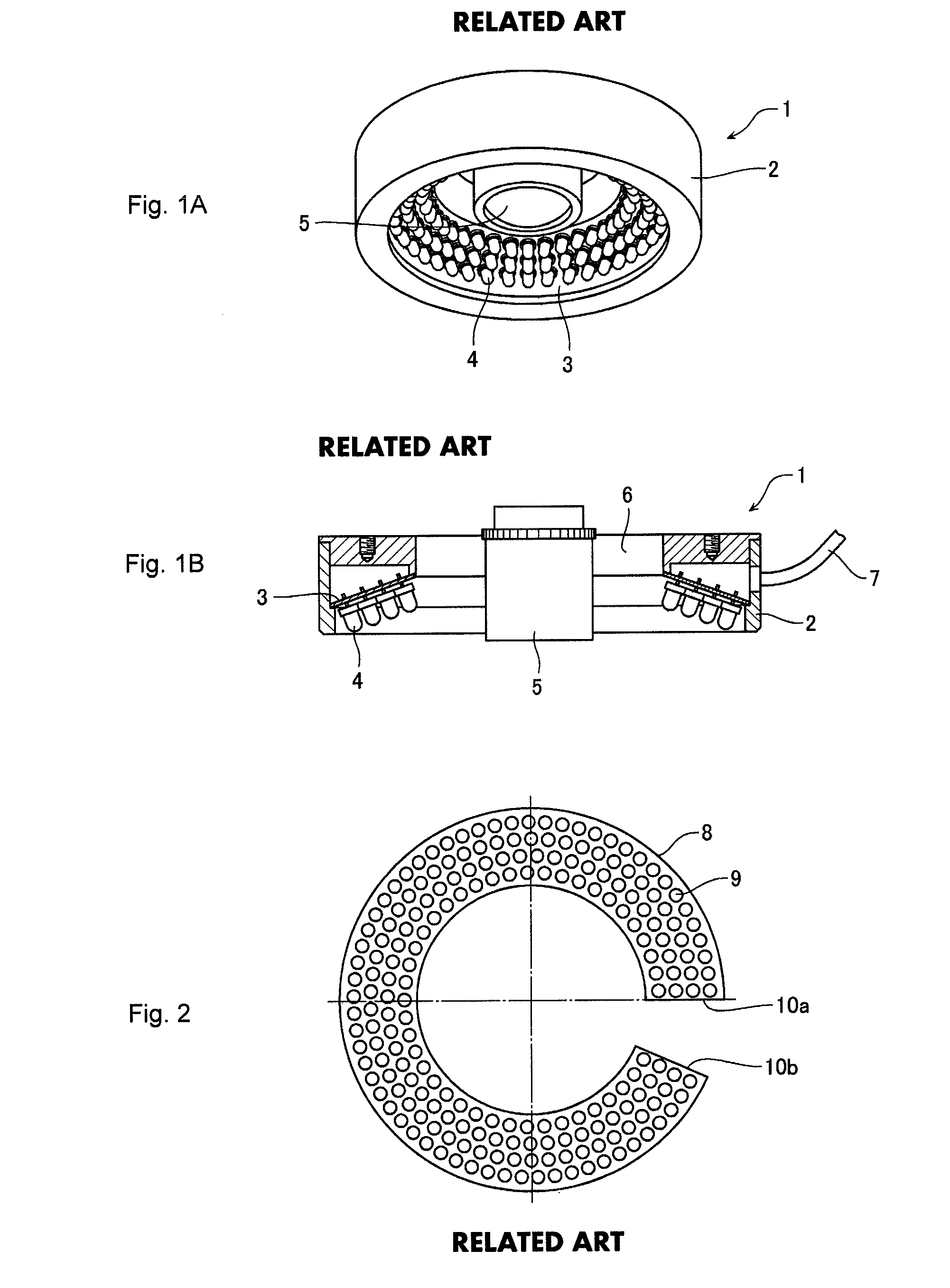
CROSS-REFERENCE TO RELATED APPLICATIONS[0001]The present application claims priority under 35 U.S.C. §119 of Japanese Application No. 2014-238386, filed on Nov. 26, 2014, the disclosure of which is expressly incorporated by reference herein in its entirety.BACKGROUND OF THE INVENTION[0002]1. Field of the Invention[0003]The present invention relates to an LED ring light used for image measuring devices and optical devices such as microscopes and a manufacture method of the LED ring light; and to an image measuring device and an optical device using the LED ring light.[0004]2. Description of Related Art[0005]For an image measuring device which captures an image of an measured object and measures the measured object based on the obtained image, and for an optical device such as an microscope observing an enlarged image of the measured object, an LED ring light is often used to illuminate the measured object.[0006]A typical LED ring light is shown in FIGS. 1A and 1B. FIG. 1A is a perspe...

Claims


Application Information

Patent Timeline
IPC IPC(8): G02B21/08F21K99/00
CPCG02B21/084F21K9/90F21K9/30
Inventor MORIUCHI, EISUKEKAWASAKI, TOSHIONISHIO, YUKIMASA
Owner MITUTOYO CORP
Why Eureka
Try Eureka