Control circuit of diode contact protection combination switch and relay control method

a control circuit and diode technology, applied in relays, electric switches, electric apparatus, etc., can solve problems such as shortened service life of switch contacts, potential surge current or voltage harmful to the power grid, and the ac switch adopting scr cannot be practical and reliable, so as to reduce contact jitters, improve the actuation speed of relay contacts, and reduce contact jitters

Active Publication Date: 2016-05-26
GYRK INT TECH
View PDF5 Cites 7 Cited by
  • Summary
  • Abstract
  • Description
  • Claims
  • Application Information

AI Technical Summary

Benefits of technology

[0014]The present invention is beneficial in that: the actuation speed of the relay contact is improved and a stress received by the contact when the actuation of the relay contact stops is reduced, so as to reduce jitters of the contact, shorten the time for the actuation of the relay contact, and significantly prolong the mechanical service life of the relay. In addition, with the control circuit and the control methods for the relay provided by this invention, it is guaranteed that the contacts of both the auxiliary relay and the primary relay can be connected within ¼ of one AC cycle as required by the diode-based contact protection circuit, so that the switch can be closed or opened at the time of a zero-crossing point of current, thereby actually achieving electrical arc extinguishing of an AC switch to substantially pr

Problems solved by technology

However, due to the time for the movement process of a mechanical contact, a mechanical contact switch cannot be closed or opened at the zero-crossing point theoretically; especially under circumstances of high voltages and high currents, severe sparking and arc discharge phenomenon occur particularly when inductive and capacitive loads are switched on and off, leading to a shortened service life of the switch contact and a potential surge current or voltage harmful to the power grid.
Nevertheless, due to power consumption and cost problems, the AC switch adopting the SCR cannot be practical and reliable.
However, the SCR is defective for a possible erroneous turning on in the case of high dv/dt and a difficulty in turning off in the case of high di/dt, the SCR composite switch has not been applied practically.
However, the circuits disclosed in these patents have strict requirements for contact travel time (i.e. duration from the time when the actuation of the contact begins to the time when the actuation of the contact fully stops) of both the secondary rel

Method used


Image

  • Control circuit of diode contact protection combination switch and relay control method
  • Control circuit of diode contact protection combination switch and relay control method
  • Control circuit of diode contact protection combination switch and relay control method

Examples


Embodiment Construction

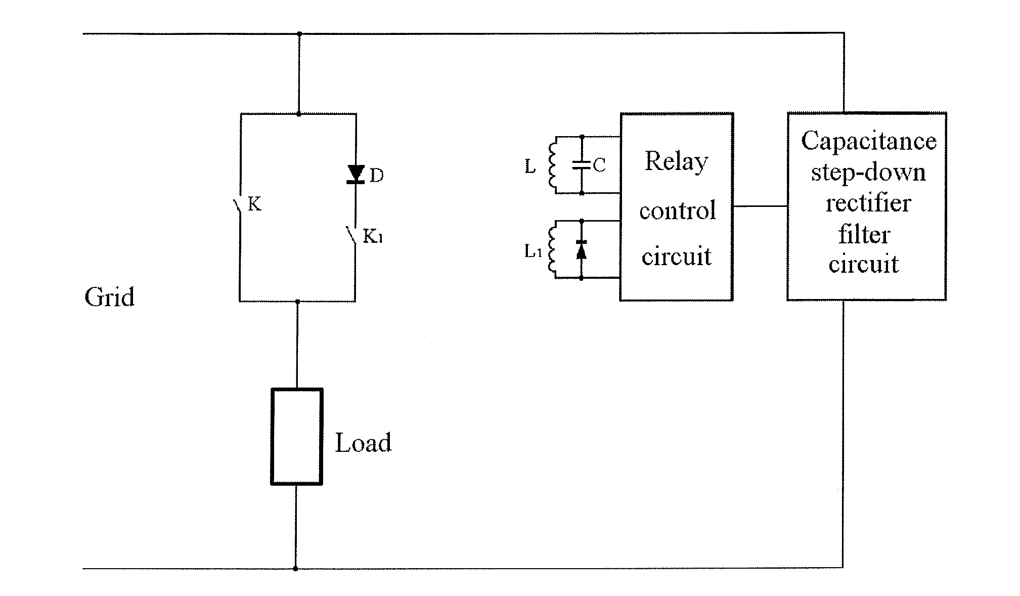
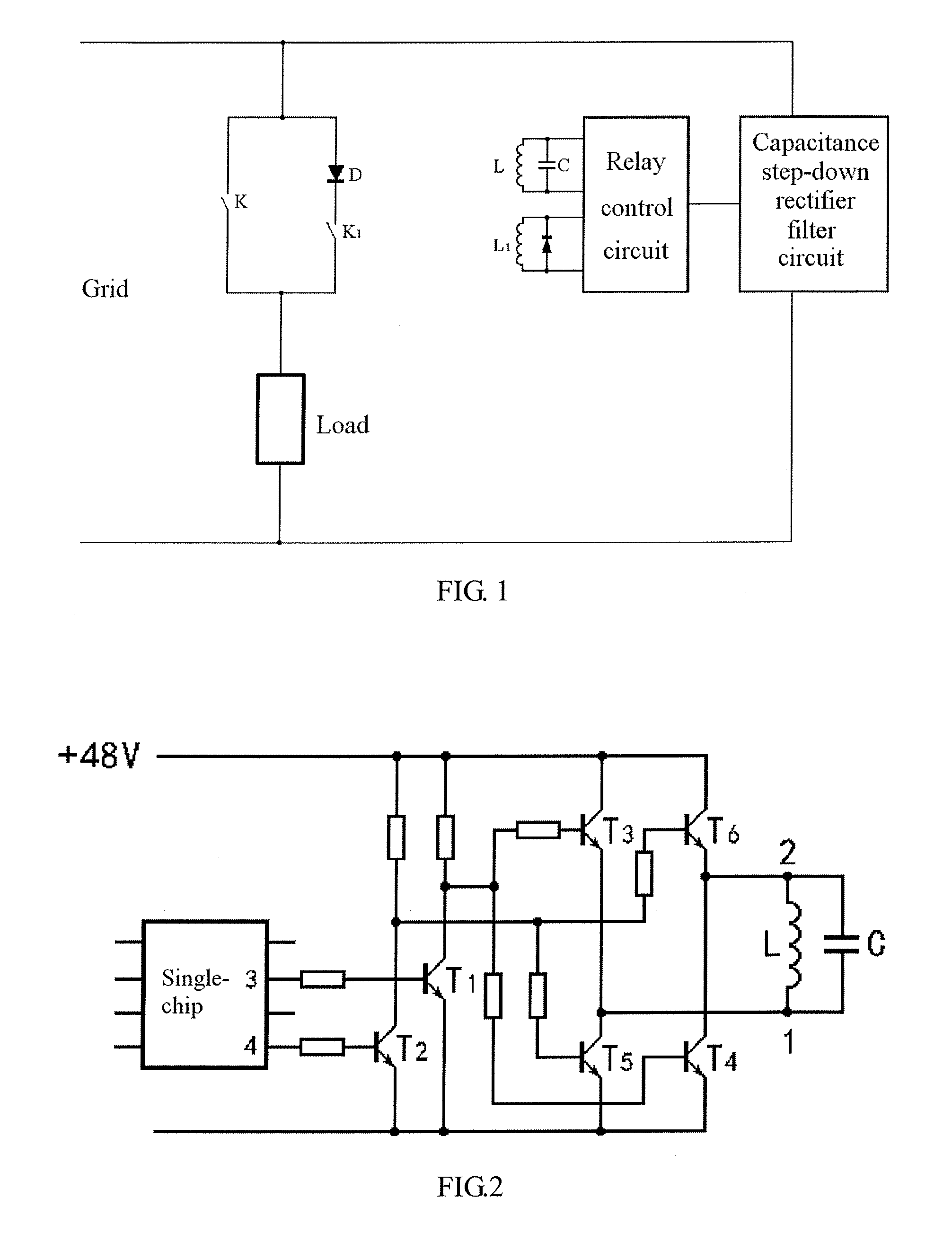
[0022]As shown in FIG. 1 which is a schematic diagram of a composite switch with contact protection based on a diode according to an embodiment of the invention, the switch includes a primary relay contact K, a contact protection diode D, an auxiliary relay contact K1 and a relay control circuit. The auxiliary relay contact K1 and the contact protection diode D are connected in series to form a primary relay contact protection circuit, which is connected in parallel at its both ends with the primary relay contact K. Since the auxiliary relay contact K1 bears the entire current at the primary relay contact at the moment when the primary relay contact K is connected or disconnected, an auxiliary relay with a current capacity same as that of the primary relay is typically considered and selected. The higher the contact current capacity of a relay is, the longer the travel time of the relay contact is. In fact, an AC switch relay with a current capacity above 20 A hardly has travel time...


PUM


Abstract

A diode contact protection combination switch and a specific implementation method. The combination switch comprises a primary contact protection circuit formed by a primary switch contact of a primary relay, diodes parallel connected at two ends of the primary switch contact, and a contact of a secondary relay. A current capacity of the secondary relay is 1/10 to 1/1000 of a current capacity of a contact of the primary relay. A drive current of the primary relay changes according to a certain rule, so as to shorten travel time of the relay. The implementation method is a control method of shortening travel time of a relay, in which a current flowing through a relay is controlled by a PWM wave output by a single chip microcomputer of a relay control circuit. The diode contact protection combination switch is an on/off switch in the case of current zero crossing, which can easily implement over-current and over-voltage protection and remote manipulation functions. By means of the relay control method, travel time when a relay is closed/opened can be greatly shortened on the premise that the service life of the relay is ensured.

Description

TECHNICAL FIELD[0001]This invention relates to an alternating current (AC) relay switch, especially to a relay switch in which a diode and a mechanical contact switch are connected in series to prevent electric arcs generated at a contact of an AC switch when the AC switch is closed or opened, as well as a relay drive circuit and a relay control method, which are classified to international classification Nos. H01H9154 and H01H9 / 56.BACKGROUND[0002]An ideal AC relay switch completes connection or disconnection of its contact at the moment of a zero-crossing point of current. However, due to the time for the movement process of a mechanical contact, a mechanical contact switch cannot be closed or opened at the zero-crossing point theoretically; especially under circumstances of high voltages and high currents, severe sparking and arc discharge phenomenon occur particularly when inductive and capacitive loads are switched on and off, leading to a shortened service life of the switch co...

Claims


Application Information

Patent Timeline
IPC IPC(8): H01H47/22H01H47/02
CPCH01H47/02H01H47/22H01H9/541
Inventor WANG, HAI
Owner GYRK INT TECH
Why Eureka
Try Eureka