
Receptacle structure

a technology of receptacle and receptacle, which is applied in the direction of coupling device connection, two-part coupling device, electrical apparatus, etc., can solve the problems of reducing the function and meaning of newly released high-speed usb plug and receptacle, affecting the stability of signal transmission, so as to improve shielding protection, stabilize the impedance variation, and control the high frequency characteristic

Active Publication Date: 2016-05-26
TRIPLE WIN PRECISION TECH
View PDF0 Cites 5 Cited by
  • Summary
  • Abstract
  • Description
  • Claims
  • Application Information

AI Technical Summary

Benefits of technology

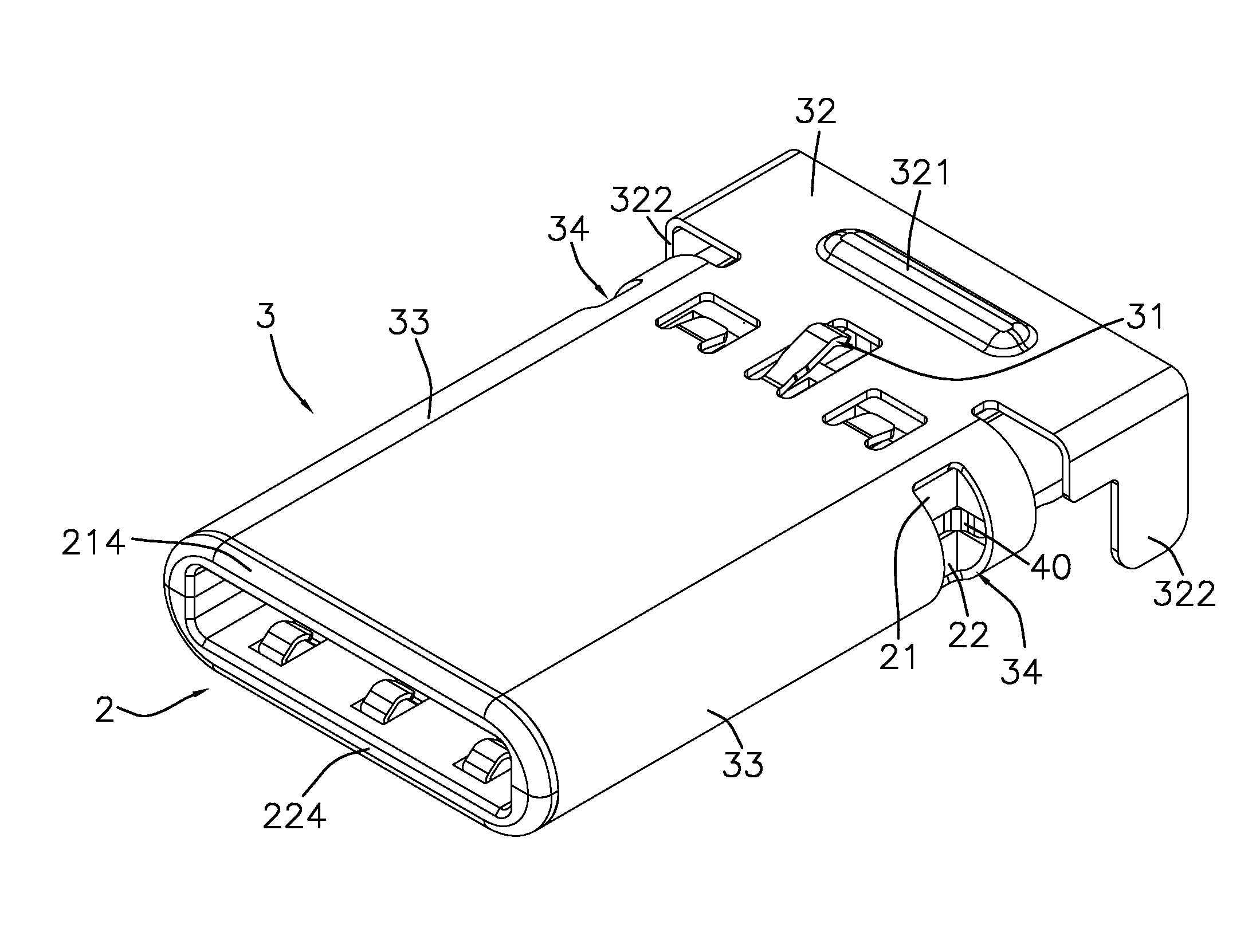
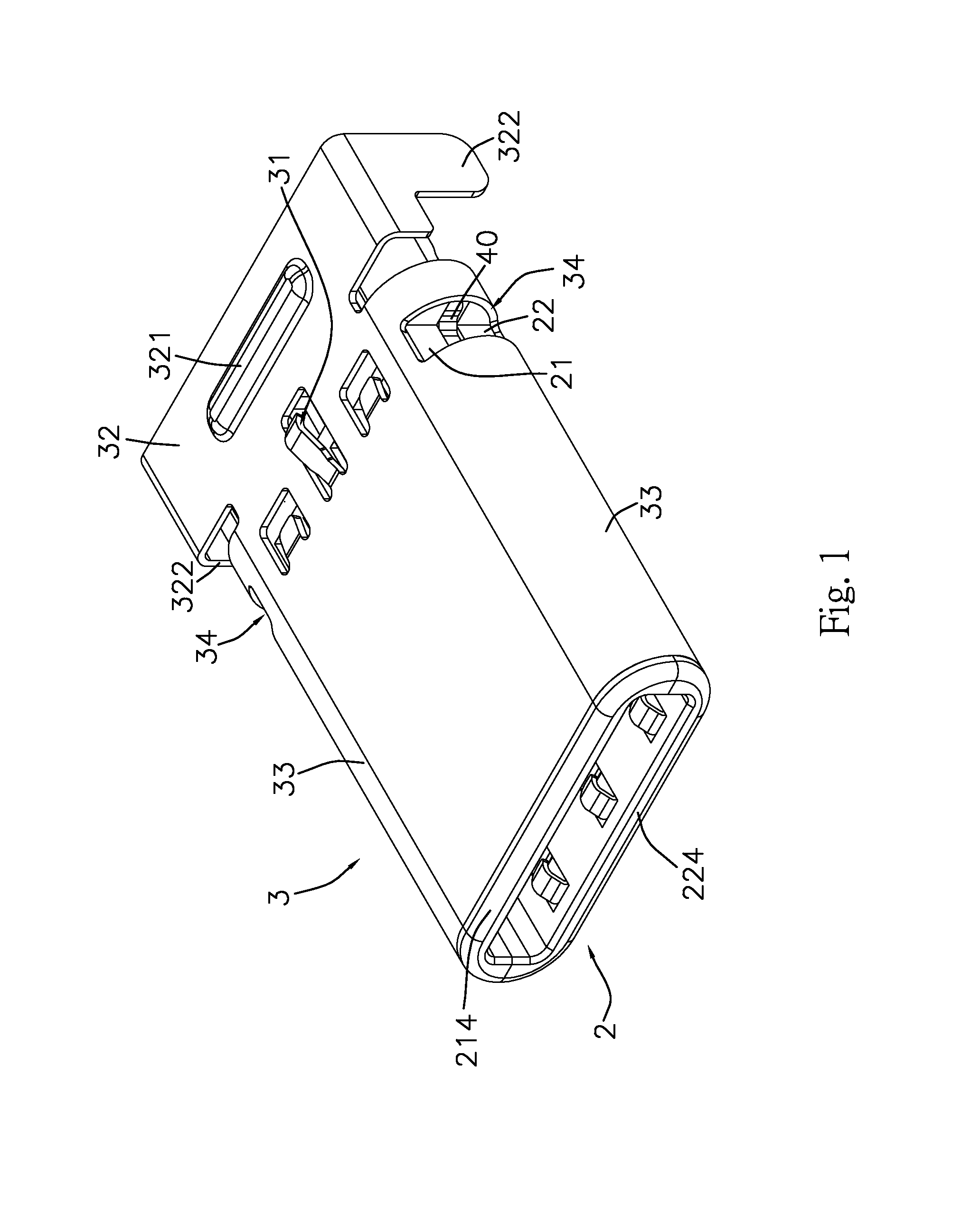
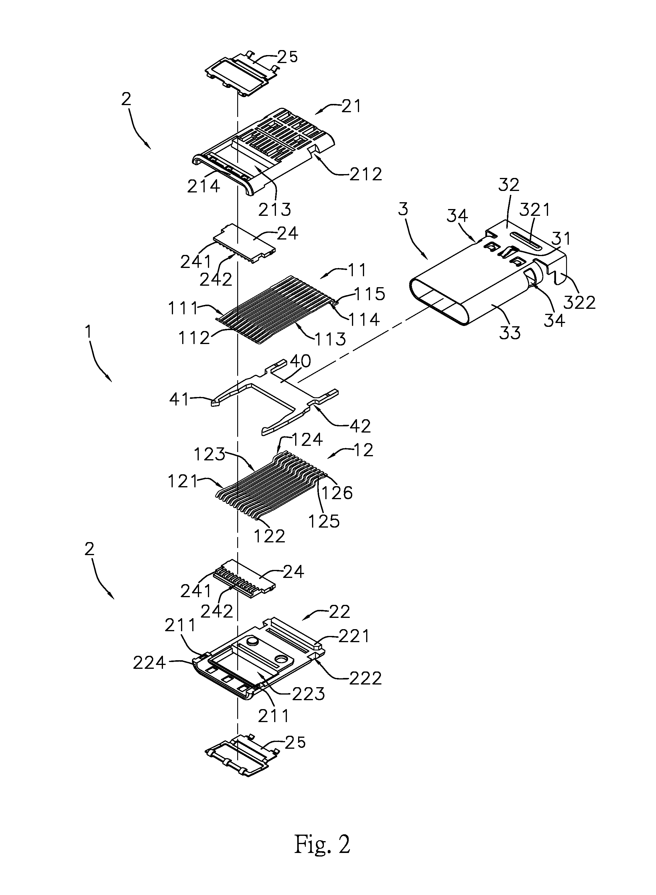
The present invention provides a design for a receptacle structure that is designed to protect against electrostatic discharge and control impedance variation. The structure includes a terminal with multiple signal pins, a main isolator, and a metallic casing. The terminal with multiple pins is surrounded by an upper and lower row termination. The main isolator consists of an upper and lower isolator. The terminal with multiple pins is positioned inside the main isolator. The metallic casing wraps around the main isolator and provides a stable shield against ESD. The casing has side curves with openings to allow for high-frequency performance. This design allows for better protection against ESD and ensures stable impedance variation within an acceptable range.

Problems solved by technology

However, the terminal with plural pins tends to interfere signal transmission due to the interior structure design.
And, under such a circumstance, the stability of signal transmission is worsened and it reduces the function and meaning of newly released high speed USB plug and receptacle.

Method used


Image

  • Receptacle structure
  • Receptacle structure
  • Receptacle structure

Examples


Embodiment Construction

[0025]Please refer to FIG. 1 to FIG. 10 which respectively illustrates those schematic views referring to a receptacle structure and is specifically applied in a structure of USB 3.1 type C. And, it is able to be applied in a SMT or DIP manufacturing process.

[0026]The present invention primarily comprises a joint assembly of terminal 1 with plural signal pins, a main isolator 2 and a metallic casing 3, wherein the terminal 1 with plural pins, configured inside the main isolator 2, is further separated with a upper row terminator 11 and a lower row terminator 12 which respectively contains twelve (12) signal pins (as shown in FIG. 3); the plural signal pins of upper row terminator 11 are bent upward at the fore-part 111 to form as a contact part 112, extends backward a section of mid-part 113, and then are bent downward at the after-part 114 and extended backward as a soldering end 115. Meanwhile, both pin width of fore-part 111 and after-part 114 in the upper row terminator 11 are w...


PUM


Abstract

A receptacle structure, which is specifically referred to a joint assembly of terminal with plural signal pins, a main isolator and a metallic casing, wherein the terminal with plural pins is further separated with an upper row terminator and a lower row terminator, the metallic casing is extended with a fixing part at the back side and is configured with an upper rib and at least a spring on the top surface of fixing part, and both laterals are formed as side curvatures with each side opening. Thus, the present invention provides a better shielding protection against ESD—Electrostatic Discharge and enables a high frequency characteristic control which stabilizes the impedance variation within the error range.

Description

BACKGROUND OF THE INVENTION[0001]1. Field of the Invention[0002]The present invention relates to an electrical receptacle structure and is especially applied in the newly specified receptacle structure of USB 3.1 Type C or similar receptacle structures.[0003]2. Description of Prior Art[0004]The USB (Universal Serial Bus) connectors had been widely adopted as a standard port to function as a transmission interface between the computer and external peripherals. Especially, USB connectors are popularly used in flash memory device and equipped with function of ‘hot plugging’ or ‘plug and play’.[0005]Following the trend to be lighter, thinner and smaller, there are several USB connectors' specification had been released and specified as standard of A type, B type, Mini USB and Micro USB. Under a global request for a unified type of electrical plug and receptacle, the USB promoter group starts a newly design and releases it as the specification of USB 3.1 type C to be wide adopted in vari...

Claims


Application Information

Patent Timeline
IPC IPC(8): H01R13/6581H01R24/60
CPCH01R13/6581H01R2107/00H01R24/60H01R12/57H01R12/72
Inventor LIU, CHIH PIN
Owner TRIPLE WIN PRECISION TECH
Learn More