
Chain plate structure

Active Publication Date: 2016-06-02
WANG WEN PIN
View PDF23 Cites 15 Cited by
  • Summary
  • Abstract
  • Description
  • Claims
  • Application Information

AI Technical Summary

Benefits of technology

The present invention relates to a gear mechanism for bicycles. It uses a reduced interval between the two limiting blocks to quickly assemble the chain-engaging tooth and guide pulley, making the shifting operation smooth. The guide pulley can displace fast and stably, preventing chain from coming off the sprocket. The invention also provides a second space between the combining portions of the link plate bodies to guide and prevent noise generated when chain hits the chain-engaging tooth. Additionally, the invention allows the chain-engaging tooth to offset transversely during shifting operation to prevent deviation and hitting the acting surface of the link plate body.

Problems solved by technology

Instead, at least one of the two kinds of teeth (B1) (C1) only gets too loose or too tight engagement with the chain (A), and this can adversely affect the efficiency of transmission and shifting operation.
However, in the prior patent, the interval between the raised portions of the two aligned chain plates is still fixed, so the problem that at least one of the two kinds of teeth only gets too loose or too tight engagement with the chain remains unsolved and the poor efficiency of transmission and shifting operation persists.

Method used


Image

  • Chain plate structure
  • Chain plate structure
  • Chain plate structure

Examples


first embodiment

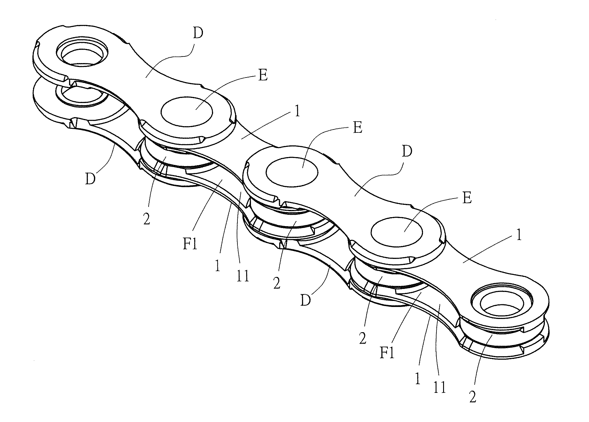
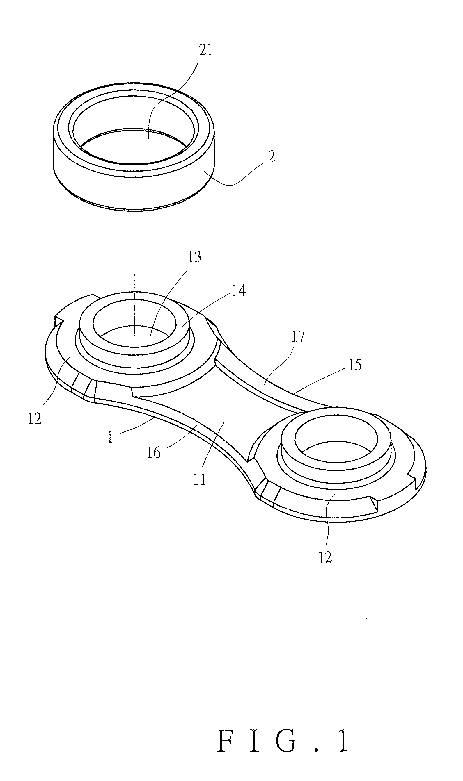
[0035]Referring to FIG. 1, in the present invention, a chain plate structure comprises a link plate body (1) and a sleeve (2).

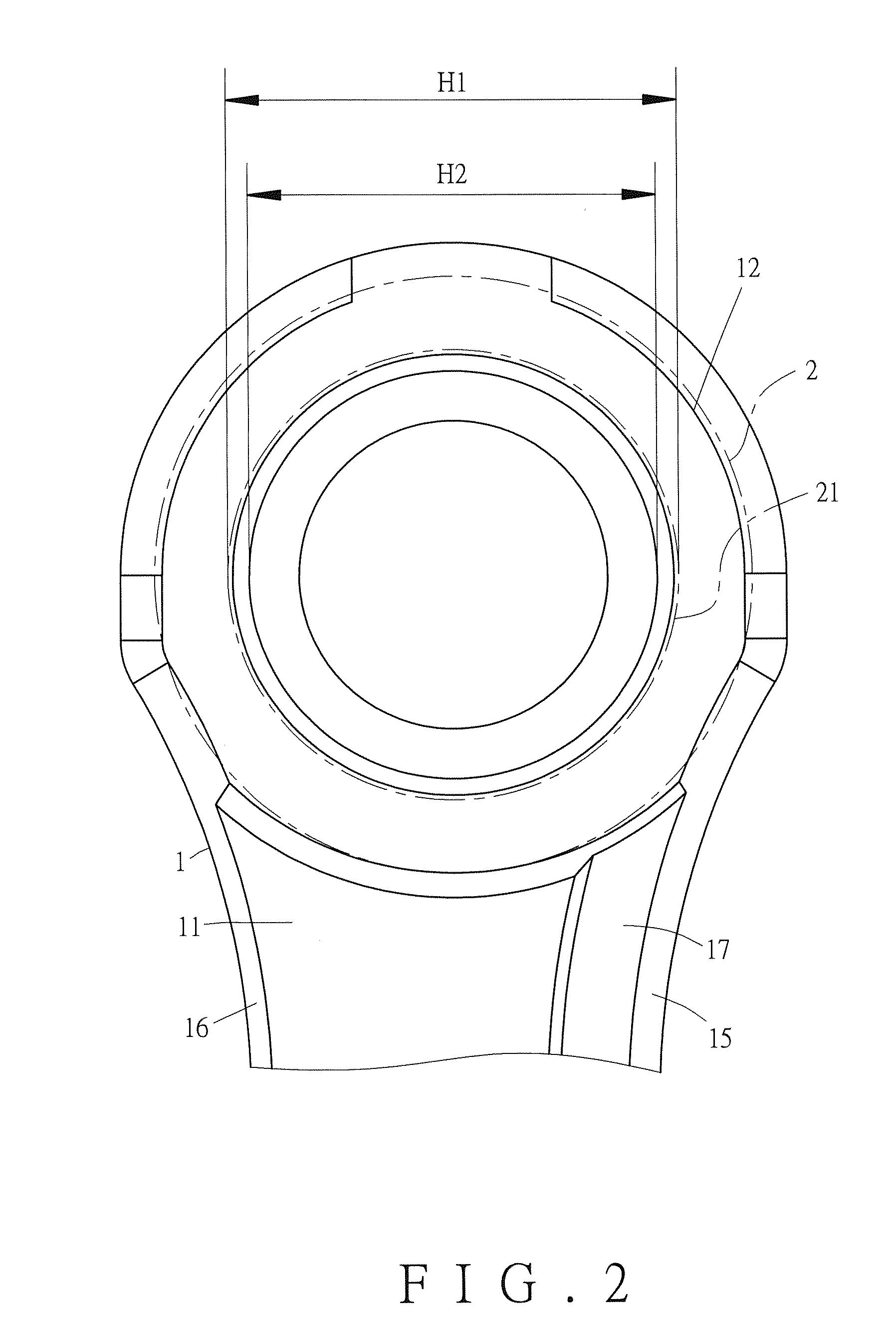
[0036]The link plate body (1) has an acting surface (11) facing another link plate body (1). The link plate body (1) has two circular combining portions (12) formed at two opposite ends of the acting surface (11). The combining portion (12) is provided with a passing-through axial hole (13). The axial hole (13) is peripherally formed with a raised ring (14). The link plate body (1) has a first approach edge (15) and a second approach edge (16), both of which extend between the two combining portions (12) on the acting surface (11). The acting surface (11) is provided with a limiting block (17) adjacent to the first approach edge (15). The limiting block (17) has an altitude higher than that of the acting surface (11) and lower than that of the combining portions (12).

[0037]The sleeve (2) is mounted on the raised ring (14) of the link plate body (1). The sleev...

second embodiment

[0041]In the present invention, as shown in FIG. 8, the link plate body (1) has an acting surface (11). The link plate body (1) has two circular combining portions (12) formed at two opposite ends of the acting surface (11). The combining portion (12) is provided with a passing-through axial hole (13). The axial hole (13) is peripherally formed with a raised ring (14). The link plate body (1) has a first approach edge (15) and a second approach edge (16), both of which extend between the two combining portions (12) on the acting surface (11). The acting surface (11) is provided with two limiting blocks (17), wherein one of the two limiting blocks (17) is adjacent to the first approach edge (15) while the other is adjacent to the second approach edge (16). The two limiting blocks (17) each have an altitude higher than that of the acting surface (11) and lower than that of the combining portions (12). With the foregoing configuration, the first and second spaces can be similarly forme...

third embodiment

[0042]In the present invention, as shown in FIG. 9, the link plate body (1) has an acting surface. The acting surface is provided with a passing-through hollowed-out portion (18). The hollowed-out portion (18) allows the chain-engaging tooth of the guide pulley or the chain-engaging tooth of the transmission sprocket to offset transversely during shifting operation, so as not to deviate and hit the acting surface of the link plate body (1). The link plate body (1) has two circular combining portions (12) formed at two opposite ends of the acting surface. The combining portion (12) is provided with a passing-through axial hole (13). The axial hole (13) is peripherally formed with a raised ring (14). The link plate body (1) has a first approach edge (15) and a second approach edge (16), both of which extend between the two combining portions (12) on the acting surface. The acting surface is provided with two limiting blocks (17), wherein one of the two limiting blocks (17) is adjacent...


PUM


Abstract

A chain plate structure includes a link plate body and a sleeve. The link plate body has an acting surface being provided with a first approach edge, two combining portions, and a limiting block located adjacent to the first approach edge. The limiting block has an altitude higher than an altitude of the acting surface. The sleeve is mounted on the link plate body and has a through hole whose maximum diameter is greater than a maximum diameter of a raised ring peripherally formed on the corresponding one of the combining portions. Therefore, when two of the link plate bodies are combined together, a first space is formed between the acting surfaces of the two aligned link plate bodies. The limiting block serves to limit the first space, while the sleeve is allowed to move on one of the combining portions so as to provide a second space.

Description

BACKGROUND OF THE INVENTION[0001]1. Technical Field[0002]The present invention relates to bicycle chains, and more particularly to a chain plate structure featuring that when the chain plate structures are assembled as a chain having plural chain elements, two spaces are formed in each said chain element, thereby contributing to steady and fast shifting operation with reduced noise.[0003]2. Description of Related Art[0004]FIG. 15 depicts an example of a conventional chain for bicycle transmission. Therein, a chain (A) routes around a derailleur's guide pulley (B) and a transmission sprocket (C), for allowing transmission and shifting operation. While the chain (A) has its each two aligned chain plates (A1) spaced by a fixed interval, the chain-engaging teeth (B1) of the guide pulley (B) and the chain-engaging teeth (C1) of the transmission sprocket (C) are different in thickness. As a result, it is impossible for the chain-engaging teeth (B1) of the guide pulley (B) and the chain-en...

Claims


Application Information

Patent Timeline
IPC IPC(8): F16G15/12F16G13/06
CPCF16G13/06F16G15/12
Inventor WANG, WEN-PIN
Owner WANG WEN PIN
Learn More