
Apparatus and method for detection

a detection device and apparatus technology, applied in the field of detection devices, can solve the problems of high manufacturing cost and affect and achieve the effect of improving the accuracy of the detection radar system

Active Publication Date: 2016-06-02
HTC CORP
View PDF0 Cites 6 Cited by
  • Summary
  • Abstract
  • Description
  • Claims
  • Application Information

AI Technical Summary

Benefits of technology

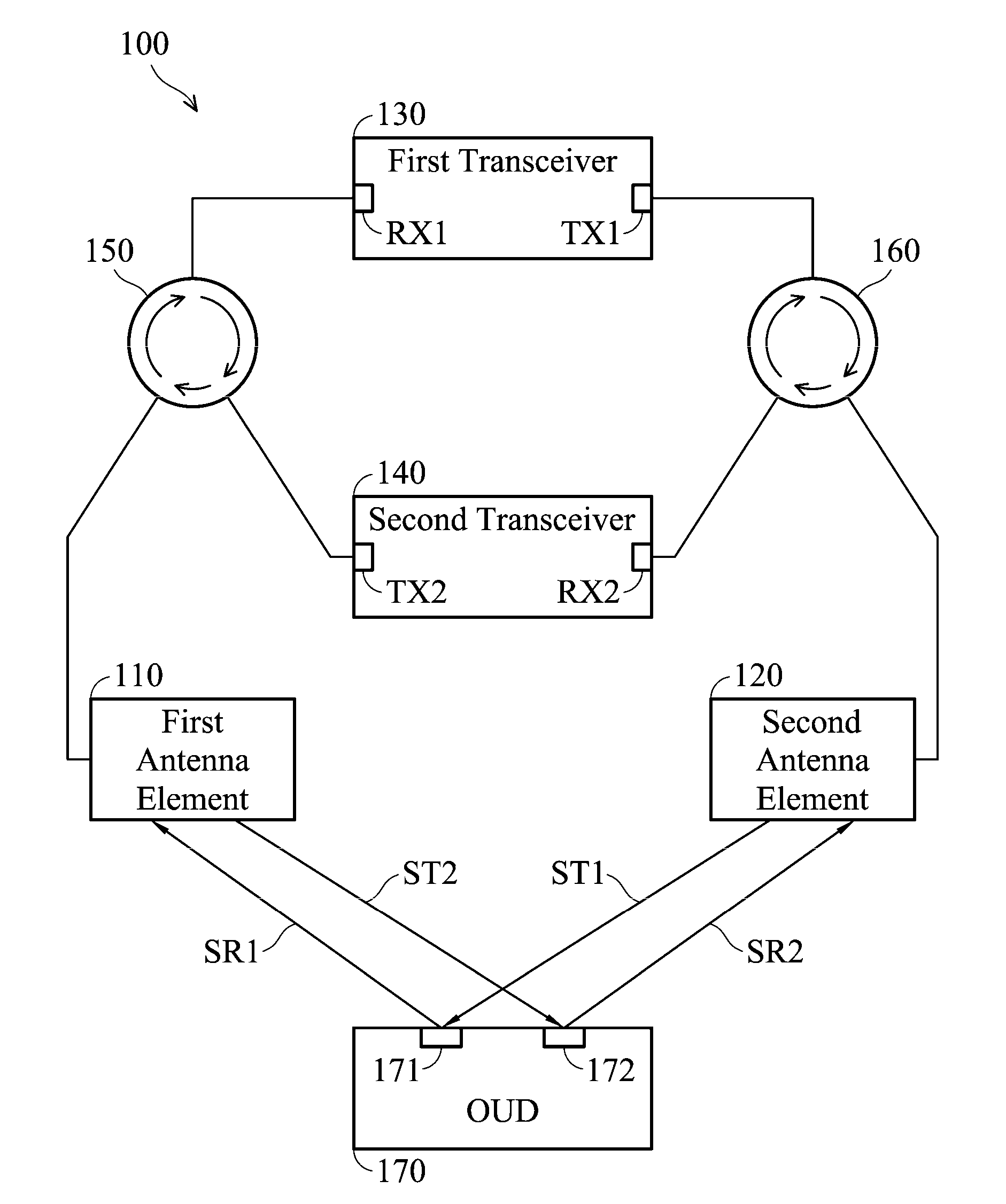
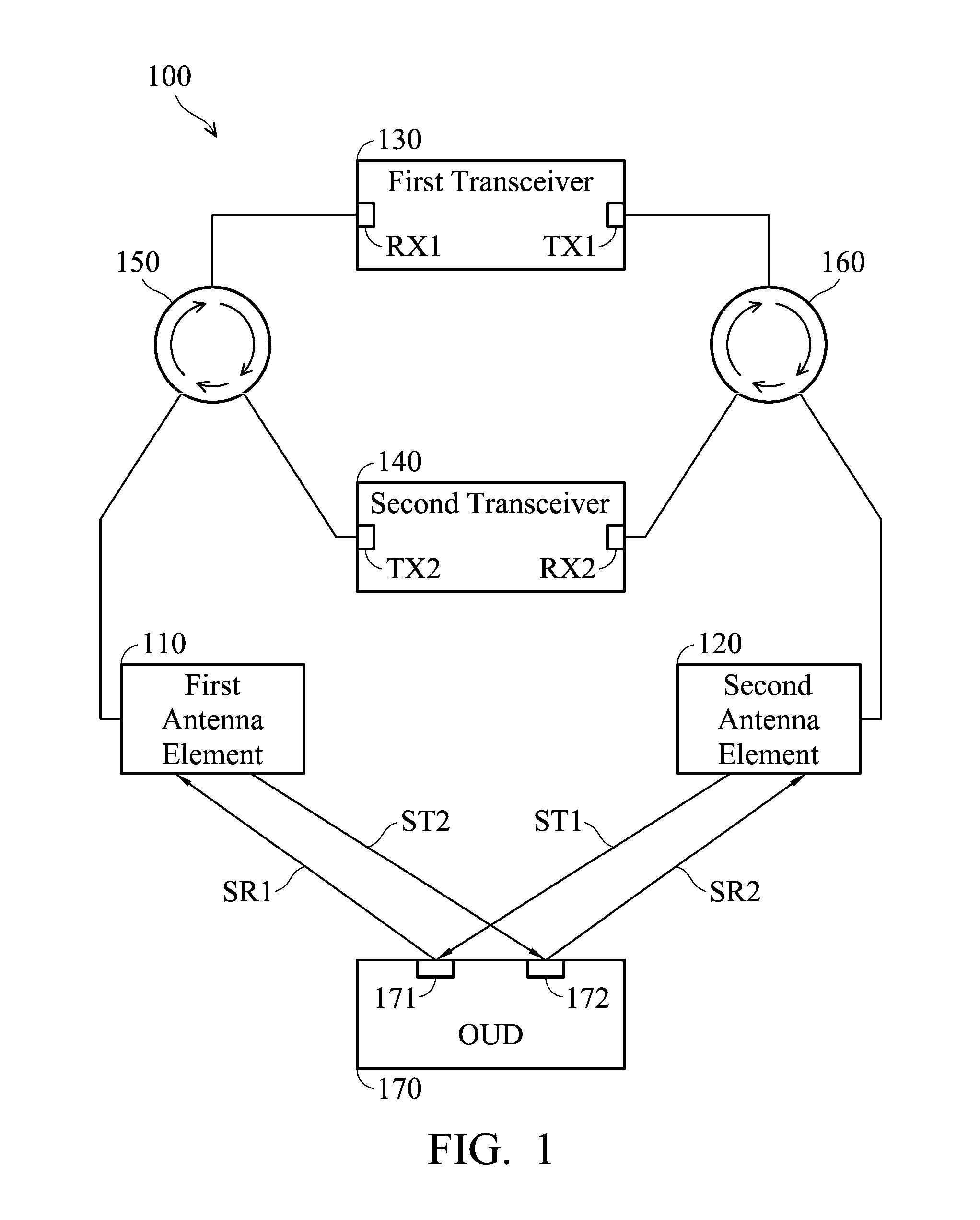
This patent is about a detection device for finding out what objects are there. The device has two antennas, two transceivers, two circulators, and a first and second antenna element. The transceivers use the circulators to transmit and receive signals to and from the antennas. The signals are directed to different regions on the object using the first and second antenna elements, which have their main lobe and null aimed at the first and second regions, respectively. The technical effect of this design is better detection and targeting of objects using signals in different directions.

Problems solved by technology

However, if more than two different regions on the OUD are required to be detected, the radar system must have multiple antennas and multiple transceivers inside, thereby resulting in a higher manufacturing cost.
In addition, the multipath fading effect of electromagnetic waves also affects the accuracy of the radar system for detection.

Method used


Image

  • Apparatus and method for detection
  • Apparatus and method for detection
  • Apparatus and method for detection

Examples


Embodiment Construction

[0013]In order to illustrate the purposes, features and advantages of the invention, the embodiments and figures of the invention are shown in detail as follows.

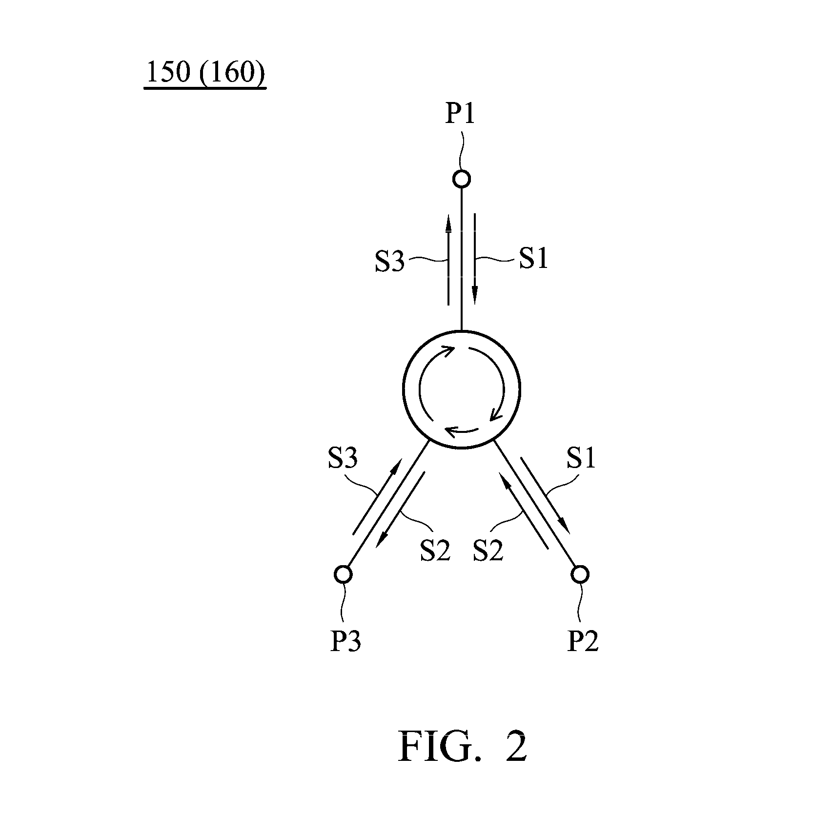
[0014]FIG. 1 is a diagram of a detection device 100 according to an embodiment of the invention. The detection device 100 may be suitable for application in the radar detection or medical field. For example, the detection device 100 can detect the position or a small movement of an OUD (Object Under Detection) 170. As shown in FIG. 1, the detection device 100 at least includes a first antenna element 110, a second antenna element 120, a first transceiver 130, a second transceiver 140, a first circulator 150, and a second circulator 160. Each of the first antenna element 110 and the second antenna element 120 may be any type of antenna, such as a monopole antenna, a dipole antenna, a loop antenna, a circular polarization antenna, an elliptical polarization antenna, or a helical antenna. The first transceiver 130 has the funct...


PUM


Abstract

A detection device for detecting an OUD (Object Under Detection) includes a first antenna element, a second antenna element, a first transceiver, a second transceiver, a first circulator, and a second circulator. The first transceiver transmits a first electromagnetic signal through the second circulator and the second antenna element to the OUD, and then receives a first reflective signal through the first antenna element and the first circulator from the OUD. The second transceiver transmits a second electromagnetic signal through the first circulator and the first antenna element to the OUD, and then receives a second reflective signal through the second antenna element and the second circulator from the OUD.

Description

BACKGROUND OF THE INVENTION[0001]1. Field of the Invention[0002]The subject application generally relates to a detection device, and more specifically, to a radar detection device.[0003]2. Description of the Related Art[0004]A conventional radar system can detect an OUD (Object Under Detection). However, if more than two different regions on the OUD are required to be detected, the radar system must have multiple antennas and multiple transceivers inside, thereby resulting in a higher manufacturing cost. In addition, the multipath fading effect of electromagnetic waves also affects the accuracy of the radar system for detection. As a result, there is a need for a novel detection device for overcoming the drawbacks of the conventional radar system.BRIEF SUMMARY OF THE INVENTION[0005]In a preferred embodiment, the subject application is directed to a detection device for detecting an OUD (Object Under Detection), and the detection device includes a first antenna element, a second ante...

Claims


Application Information

Patent Timeline
Patent Type & Authority Applications(United States)
IPC IPC(8): G01S13/04A61B5/05G01S7/02
CPCG01S13/04A61B5/05G01S7/026G01S7/03A61B5/0507A61B5/1135A61B2562/0228G01S13/56G01S7/032
Inventor PU, TA-CHUNWU, CHUN-YIHKUO, YEN-LIANG
Owner HTC CORP
Learn More