Shielded cable

a shielded cable and cable technology, applied in the direction of insulated conductors, power cables, cables, etc., can solve the problems of impaired flexibility of shielded cables, and achieve the effects of preventing signal dip, flexible, and easy to bend

Active Publication Date: 2016-06-02
SUMITOMO ELECTRIC IND LTD
View PDF4 Cites 14 Cited by
  • Summary
  • Abstract
  • Description
  • Claims
  • Application Information

AI Technical Summary

Benefits of technology

[0009]According to the shielded cable of the invention, it is possible to provide a shielded cable having a shielding conductor applied onto the circumference of a plurality of insulated wires, which prevents dip of signal in a high frequency region and is easy to bend and flexible.

Problems solved by technology

However, when the metal foil and resin tape is spirally wrapped in a state that a part thereof is overlapped, flexibility of the shielded cable is impaired.

Method used


Image

  • Shielded cable
  • Shielded cable
  • Shielded cable

Examples


example 1

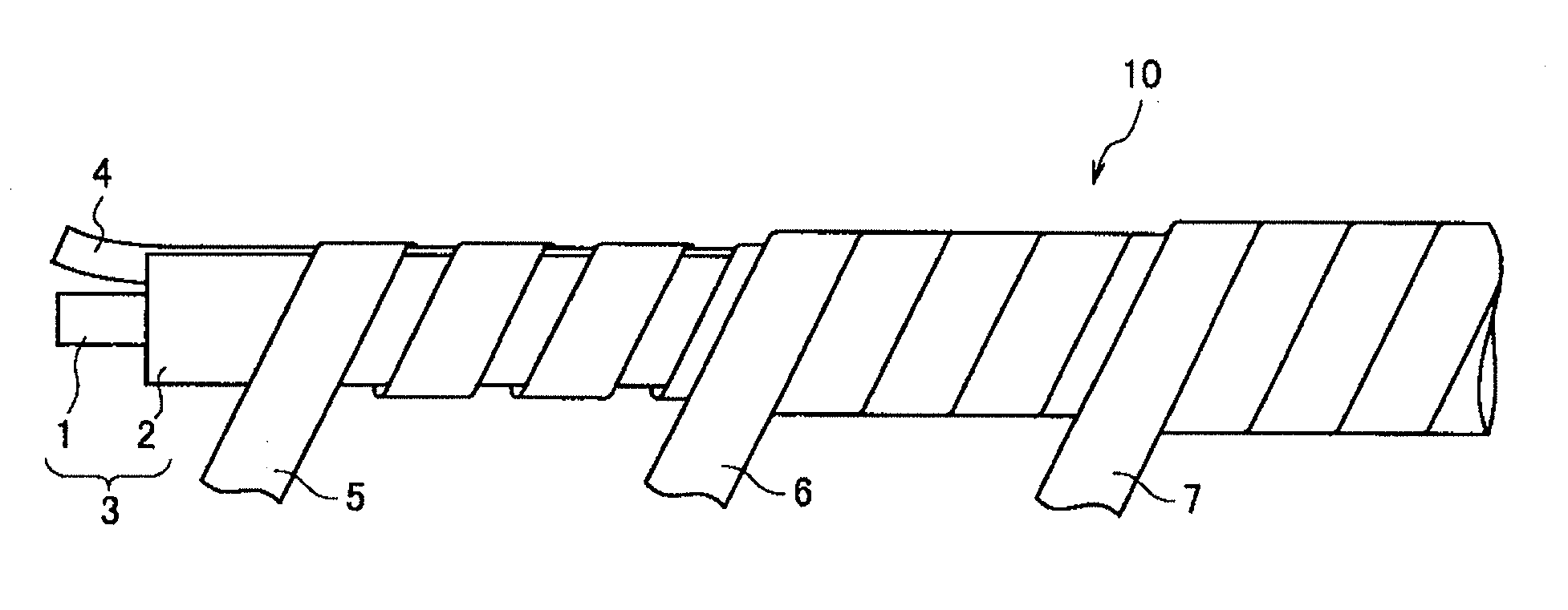
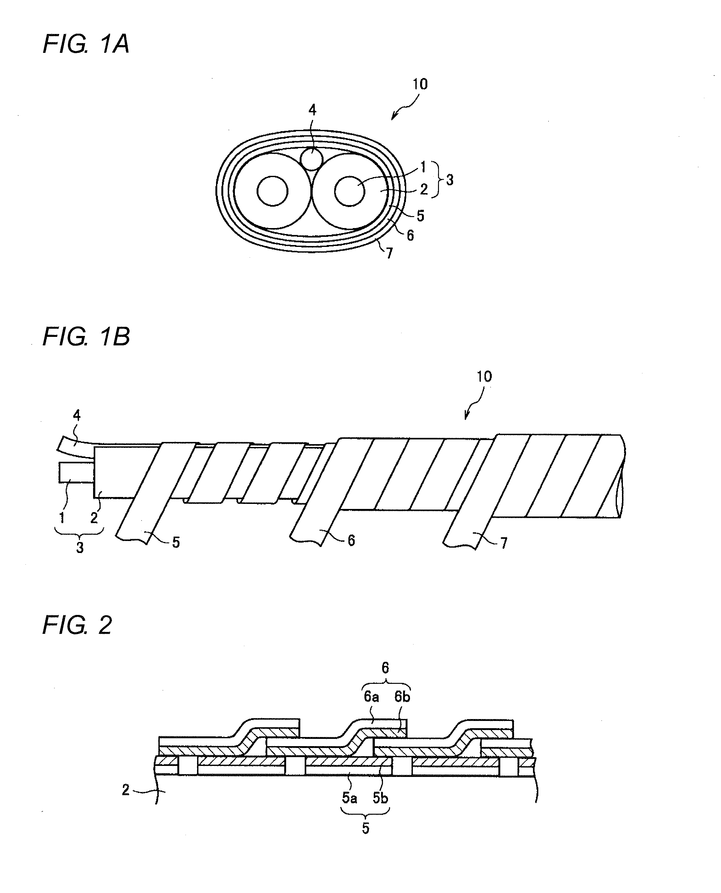
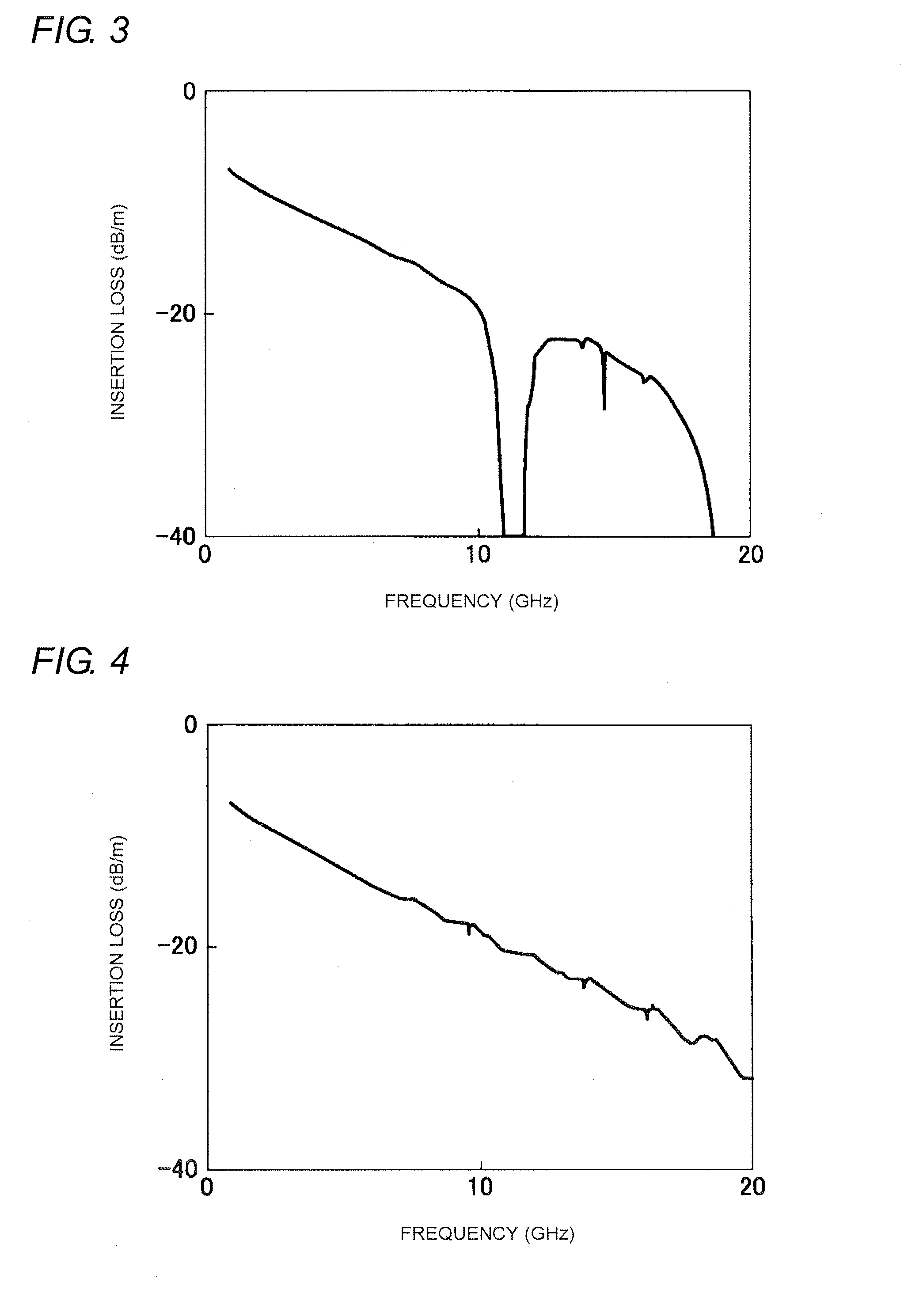
[0036]A sample was prepared according to the configuration described in FIG. 1A and FIG. 1B, and transmission characteristics were examined.

[0037]As for the configuration of the sample, two insulated wires 3 were arranged in parallel. Each of the insulated wire 3 had a diameter of 1.2 mm. An insulator 2 composed of foamed PE was provided around a signal conductor 1 corresponding to AWG 26, and thereby the insulated wire 3 was obtained.

[0038]The first metal clad resin tape 5 was formed by lamination of an aluminum foil and PET, and the thickness was 15 pm and the width was 4 mm. The second metal clad resin tape 6 was similarly formed by lamination configuration of an aluminum foil and PET, and the thickness was 15 μm and the width was 10 mm. The thickness of the metal foil was 9 μm.

[0039]Then, on the circumference of the insulated wire 3, the first metal clad resin tape 5 was wrapped spirally by open-wrapping while the metal layer thereof was positioned outside and furthermore, the s...

example 2

[0064]Samples were prepared according to the configuration described in FIG. 5A and FIG. 5B, and transmission characteristics were examined.

[0065]As for the configuration of the sample, two insulated wire 3 were arranged in parallel. Each of the insulated wire 3 had a diameter of 1.2 mm. An insulator 2 composed of foamed PE was provided around a signal conductor 1 corresponding to AWG 26, and thereby the insulated wire 3 was obtained. The first metal clad resin tape 5 was formed by lamination of an aluminum foil and PET, and the thickness was 15 μm and the width was 4 mm. The second metal clad resin tape 6 was similarly formed by lamination configuration of an aluminum foil and PET, and the thickness was 15μm and the width was 10 mm. The thickness of the metal foil was 9 μm.

[0066]Then, on the circumference of the insulated wire 3, the first metal clad resin tape 5 was wrapped spirally by open-wrapping while the metal layer thereof was positioned outside and furthermore, the second m...


PUM

PropertyMeasurementUnit
dielectric constantaaaaaaaaaa
areaaaaaaaaaaa

Abstract

A shielded cable comprising two insulated wire covered with first and second metal clad resin tapes each of which has a laminated metal layer and a resin layer. The first metal clad resin tape covers the circumference of the two insulated wires by open-wrapping and the second metal clad resin tape is spirally wrapped around the circumference of the first metal clad resin tape. The first and second metal clad resin tapes are disposed while the metal layers face each other and, in the portion where the second metal clad resin tape is overlapped by wrapping, the metal layer of the overlapped one second metal clad resin tape and the metal layer of the other second metal clad resin tape are in contact with the first metal clad resin tape. The shielded cable can prevent sharp signal attenuation in a high frequency region and is easy to bend and flexible.

Description

CROSS-REFERENCE TO RELATED APPLICATION[0001]The present application claims the benefit of priority of Japanese Patent Application No. 2014-240983, filed on Nov. 28, 2014, which is incorporated herein by reference.TECHNICAL FIELD[0002]The present invention relates to a shielded cable and more specifically, it relates to a shielded cable in which a shielding conductor composed of a metal clad resin tape is applied onto the circumference of two or more insulated wires.BACKGROUND ART[0003]FIG. 11A and FIG. 11B are views showing a configuration of one example of a conventional shielded cable which is disclosed in Japanese patent publication 2014-17131A.[0004]Two insulated wires (signal wires) 4 in which a signal conductor 2 composed of a twisted wire is covered with an insulator 3 having a predetermined dielectric constant are arranged in parallel. To the two insulated wires 4 arranged in parallel. On the outer circumference of the two insulated wires, a metal foil and resin tape 5 posse...

Claims


Application Information

Patent Timeline
Patent Type & Authority Applications(United States)
IPC IPC(8): H01B9/02H01B7/04H01B3/00H01B11/00H01B11/06
CPCH01B9/025H01B11/002H01B7/04H01B3/004H01B11/06H01B11/183H01B11/203
Inventor MATSUDA, MOTOIKARUBE, KATSUMIKOBAYASHI, YUTOENDO, TAKAKIARAKAWA, YOSHIAKIMATSUSHITA, HAYATO
Owner SUMITOMO ELECTRIC IND LTD
Why Eureka
Try Eureka