Rack component and rack system

a technology of components and racks, applied in the field of rack components, can solve the problems of affecting the quality of workpieces, and reducing the efficiency of building workpieces, so as to reduce the thickness, reduce the cost, and save materials.

Active Publication Date: 2016-06-09
VURN INNOVATION LLC
View PDF20 Cites 0 Cited by
  • Summary
  • Abstract
  • Description
  • Claims
  • Application Information

AI Technical Summary

Benefits of technology

[0015]Although the component body can be solid across its width, it may be formed in an I-beam construction, with the edges having the full width and the middle having a reduced thickness to conserve material. Notwithstanding, it is preferred that an area surrounding the aperture extend to at least the width of one side of the component body, and preferably extend beyond the width of the component body to minimize contact with the door when the door and component body are being pivoted about the fastener. It is most preferred that the opposed side of the aperture be recessed from the width, and preferably recessed a sufficient distance so that the recess can retain and support a dowel spanning two rack components, for hanging workpieces if desired.
[0016]The component body may be made of any suitable material that can provide structural integrity to the workpiece or stacked workpieces being supported, including wood, metal, plastic or the like, as well as combinations thereof. Most preferably, the component body is formed of an integrally formed plastic material by injection molding, to reduce the costs.

Problems solved by technology

Workers finishing building workpieces such as doors, trim, moldings and the like during building or renovations, including painting, staining, sealing, or the like, often experience difficulties due to the awkward shapes and need to finish more than one side of the piece or pieces.
Moreover, because of the size of most doors, finishing multiple doors often requires significant space to lay the doors down with the finish side up so that the finish side does not come in contact with other pieces, tools, brushes, drop cloths, etc., during the drying process.
Devices used to finish and stack workpieces have been primarily limited to saw horses, work benches, boards and the like, which are themselves not only space consuming when in use, but also space consuming when not in use and need to be stored.
However, this still requires that the edges be unfinished, and can lead to imperfections in the finish where a piece rests against an adjacent piece.
However, this quickly leads to the use of all available floor or wall space, leaving the worker without sufficient room.
Therefore, there is a failure in the art to provide a solution for permitting a user to finish doors, trim, molding and other pieces quickly and efficiently, and minimizing the space needed to dry multiple pieces as they are finished.

Method used


Image

  • Rack component and rack system
  • Rack component and rack system
  • Rack component and rack system

Examples


Embodiment Construction

[0025]The following description of the preferred embodiment is presented to describe the present invention without limiting the scope of the appended claims in any manner whatsoever.

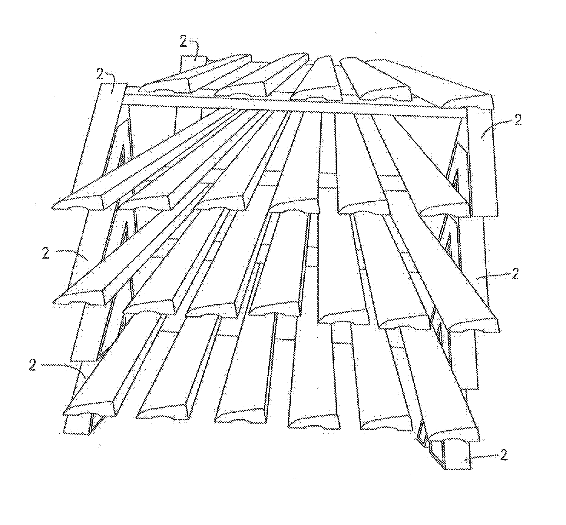
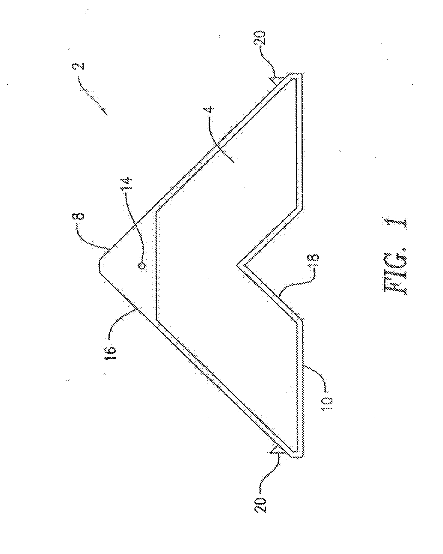
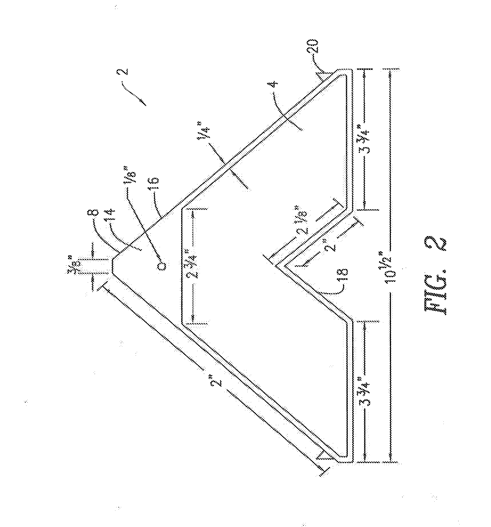
[0026]As shown in FIGS. 1-5, the present claimed invention is directed to a rack component, used as part of a rack system, where the rack component comprises a component body 2 having a front 4, a back 6, a top 8, a base 10, a width 12 between the front 4 and the back 6, and an aperture 14 near the top extending through the component body 2, wherein the top 8 of the component body comprises a top configuration 16 that is the negative of a bottom configuration 18 on the base 10 of the component body 2, such that the bottom configuration 18 on the base 10 of one component body 2 can receive the top configuration 16 on the top 8 of an adjacent component body 2.

[0027]In the most preferred embodiment, the component body 2 is generally in the shape of triangle with first and second sides of substantially equal...


PUM

PropertyMeasurementUnit
widthaaaaaaaaaa
widthaaaaaaaaaa
widthsaaaaaaaaaa

Abstract

A rack component having a component body with a front, back, top, base, width between the front and the back, and an aperture extending through the component body near the top, the top of the component body configured to be the negative of a cut-out on the base, such that the cut-out on the base of one component body can receive the configuration on the top of an adjacent component body below it. A rack system using a series of the rack components is also disclosed.

Description

FIELD OF THE INVENTION[0001]The present invention relates to a rack component and, more particularly, to a rack component that can be used with similar rack components for stacking doors, moldings and related materials during the finishing process.BACKGROUND OF THE INVENTION[0002]Workers finishing building workpieces such as doors, trim, moldings and the like during building or renovations, including painting, staining, sealing, or the like, often experience difficulties due to the awkward shapes and need to finish more than one side of the piece or pieces. For example, when finishing a door, a worker generally needs to paint a first side, wait for that side to dry and then finish the other side. Moreover, because of the size of most doors, finishing multiple doors often requires significant space to lay the doors down with the finish side up so that the finish side does not come in contact with other pieces, tools, brushes, drop cloths, etc., during the drying process.[0003]Devices...

Claims


Application Information

Patent Timeline
Patent Type & Authority Applications(United States)
IPC IPC(8): A47B47/00A47B47/04A47B47/02A47B45/00
CPCA47B47/0091A47B47/02A47B47/04A47B45/00B65G1/14A47B47/047B65G1/02B65C1/02
Inventor VALLIERE, MARC DENISBURNS, MATTHEW DAVID
Owner VURN INNOVATION LLC
Why Eureka
Try Eureka