Bone plate for reducing angular bone deformity and method of using

a bone plate and angular bone technology, applied in the field of bone plate, can solve the problems of severe weakening of the bone, difficult drilling of the centerline of the second metatarsal, and more difficult procedures, so as to correct and reduce angular bone deformities, the effect of reducing angular bone deformities

Active Publication Date: 2016-06-09
FASTFORWARD SURGICAL
View PDF3 Cites 8 Cited by
  • Summary
  • Abstract
  • Description
  • Claims
  • Application Information

AI Technical Summary

Benefits of technology

[0010]Embodiments of the present invention satisfy this need in the form of a method and device that allows for the correction and reduction of angular bone deformities using a tethering technique which does not require drilling into the stable bone. The devices and methods described herein can also allow for the reduction of angular bone deformities without requiring the placement of a prominent suture knot/button device medially along the unstable bone. For example, in some embodiments, the devices and methods described herein can be used to reduce angular bone deformities such as metatarsus primus adductus, hallux valgus, Tailor's bunion,

Problems solved by technology

However, each of these references suffers from one or more of the following disadvantages: a hole must be drilled into or through the second metatarsal, to secure one end of the tethering device while the other (medial) end of the tethering device is secured with a button.
Drilling a hole through the second metatarsal, which is significantly smaller in diameter by comparison to the first metatarsal, severely weakens the bone.
Nevertheless, drilling a hole through the centerline of the second metatarsal is especially difficult because it is done at an angle through a hole in the first metatarsal.
Making the procedure more difficult, the drilling must be done with little or no visibility.
A second metatarsal bone which has been drilled through is more vulnerable to stress and/or fracture from tension caused by the tethering techniques.
Fracture of the second metatarsal is a common and potentially devastating complication of these tethering techniques.
Additionally, the use of bu

Method used


Image

  • Bone plate for reducing angular bone deformity and method of using
  • Bone plate for reducing angular bone deformity and method of using
  • Bone plate for reducing angular bone deformity and method of using

Examples


Embodiment Construction

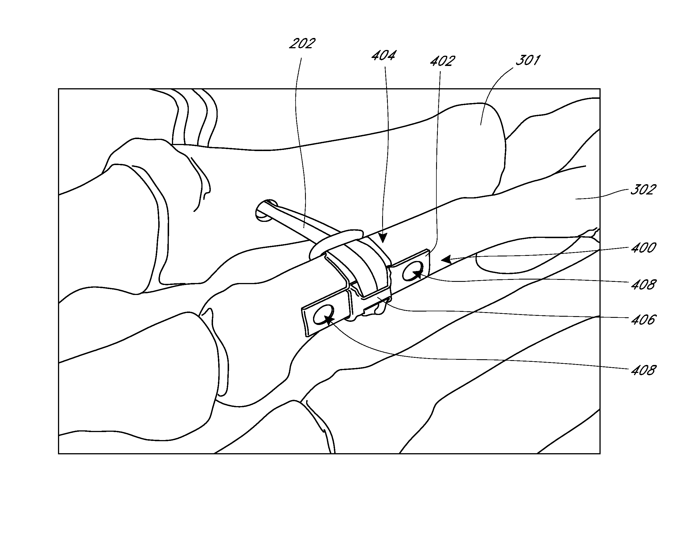
[0039]In various situations, a surgeon may need or wish to tie (or lasso) cerclage material around one bone then secure the other end of the cerclage material (under tension) to an adjacent bone for stabilization or to reduce an angular deformity between the two bones. However, if the cerclage material is tied around a bone and is in direct contact with that bone, then there is risk of fracturing that bone once tension is placed on the cerclage material. Furthermore, when some cerclage material, such as suture tape, is tied around unprotected bone and then anchored to another bone using a tethering technique, any motion between the two bones can cause friction between the cerclage material and the unprotected bone. This friction can cause adverse effects such as periosteal reaction (rope burn) and possible stress fracture. The winged bone plates described herein advantageously protect the bone from two harmful forces: tension and friction. The elongate plate body distributes tension...


PUM


Abstract

Described herein are methods sand devices for the correction and reduction of bone deformities, such as metatarsus primus adductus, using a tethering technique which does not require drilling into the stable bone. In some embodiments, a bone plate has an elongate plate body and wings extending laterally from the plate body. The wings may be configured to generally follow the circumferential contours of the bone when placed on the bone in use. The bone plate can further include means for positioning cerclage material on the bone plate such that the cerclage material extends circumferentially over the wings rather than on the bone, thereby reducing the total contact area between the cerclage material and the bone.

Description

INCORPORATION BY REFERENCE TO ANY PRIORITY APPLICATIONS[0001]This application claims the benefit of U.S. Provisional Application No. 61 / 846,760, filed Jul. 16, 2013, the entirety of which is hereby incorporated by reference. The disclosure of this application is also related to U.S. Provisional Application No. 61 / 672,297 filed on Jul. 17, 2012, U.S. Provisional Application No. 61 / 713,443 filed on Oct. 12, 2012, and to U.S. application Ser. No. 13 / 720,826, filed Dec. 19, 2012 and published as 2014 / 0025123 A1 on Jan. 23, 2014. Each of these applications is hereby incorporated by reference in its entirety.BACKGROUND OF THE INVENTION[0002]1. Field of the Invention[0003]Embodiments of the invention relate to surgical implant devices for repairing or reducing angular bone deformities. In some embodiments, the devices can be used for reducing angular bone deformities such as metatarsus primus adductus. While certain embodiments of the invention were conceived for the purposes of correcting...

Claims


Application Information

Patent Timeline
IPC IPC(8): A61B17/80A61B17/82A61B17/04
CPCA61B17/8061A61B17/82A61B17/0469A61B17/842A61B2017/565
Inventor ZEETSER, VLADIMIRBURATTI, DAWN
Owner FASTFORWARD SURGICAL
Why Eureka
Try Eureka