Scissor lift table and method for changing a fixed bearing of a scissor lift table

Active Publication Date: 2016-06-09
MOHR CHRISTOPH
View PDF8 Cites 7 Cited by
  • Summary
  • Abstract
  • Description
  • Claims
  • Application Information

AI Technical Summary

Benefits of technology

[0016]The temporary pivot axis is advantageously provided using a fixing device. The fixing device is especially means that may be connected with the lift table for providing a temporary pivot a

Problems solved by technology

This subjects the bearings of the lift table, especially the fixed bearing, to noticeable wear.
But even with such a lift table, there is still the problem of changing the fixed bearings.
Since the fixed bearings permanently bear the lo

Method used


Image

  • Scissor lift table and method for changing a fixed bearing of a scissor lift table
  • Scissor lift table and method for changing a fixed bearing of a scissor lift table
  • Scissor lift table and method for changing a fixed bearing of a scissor lift table

Examples


Embodiment Construction

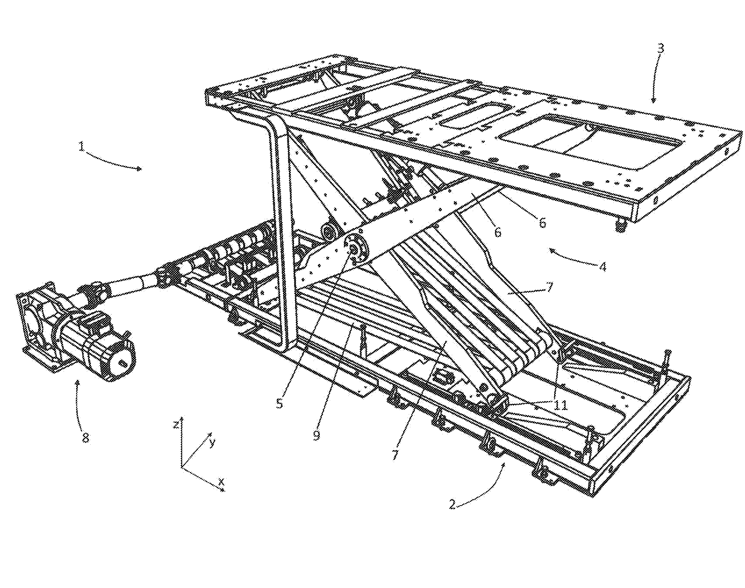
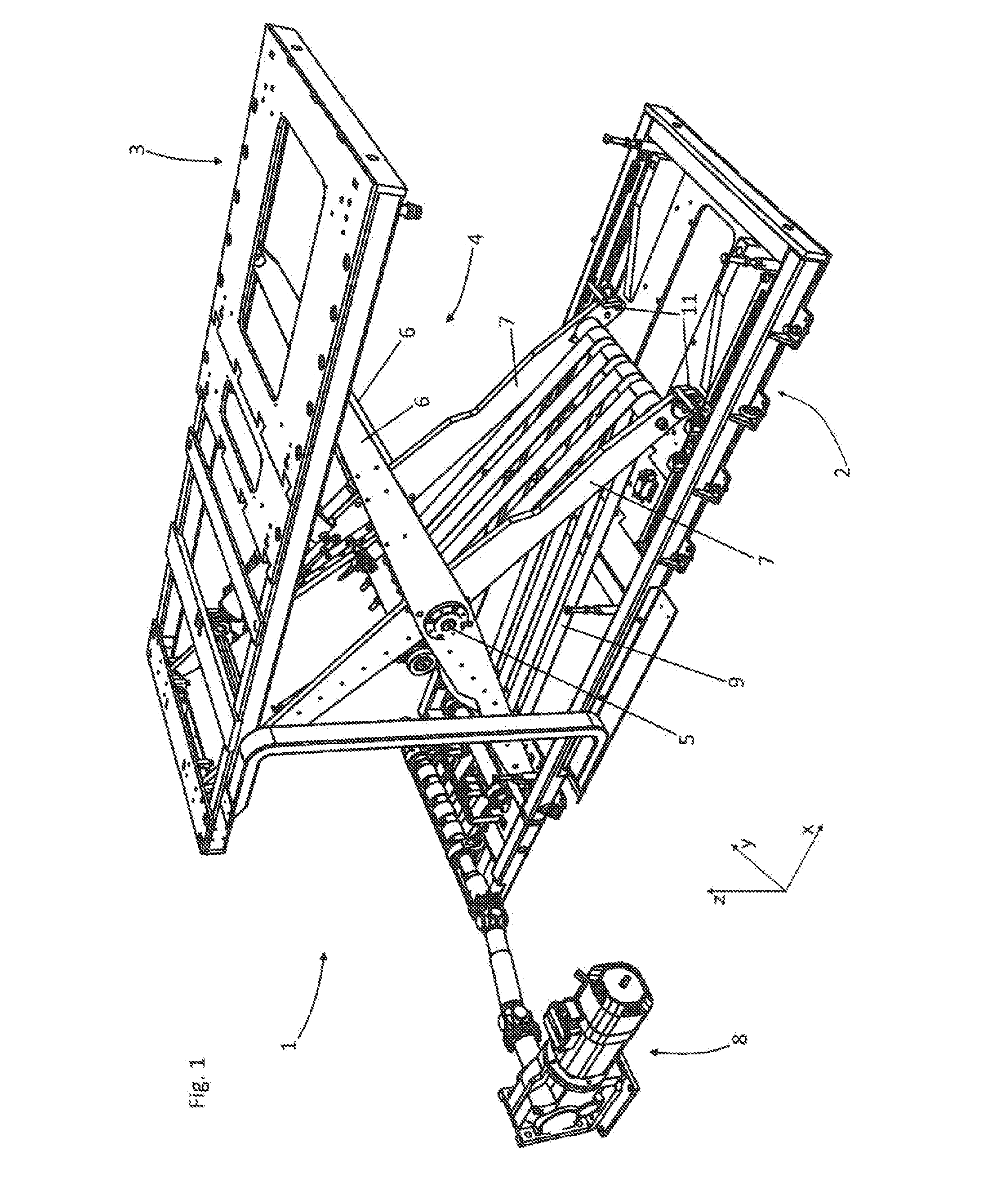
[0022]The exemplary inventive lift table depicted in FIG. 1 has a first base element 2 and a second base element 3 that are connected by a scissor 4. The scissor 4 has a first scissor part 6 and a second scissor part 7 that are connected by a pivot axis 5. In the example shown, each scissor part is essentially made of two scissor blades and transverse connecting elements for connecting the scissor blades.

[0023]For lifting and lowering the lift table, the exemplary inventive lift table has a drive 8 that acts on the scissor 4 via a tensioning means 9, the latter in the example shown being embodied as an arrangement of belt straps that may be wound on a shaft.

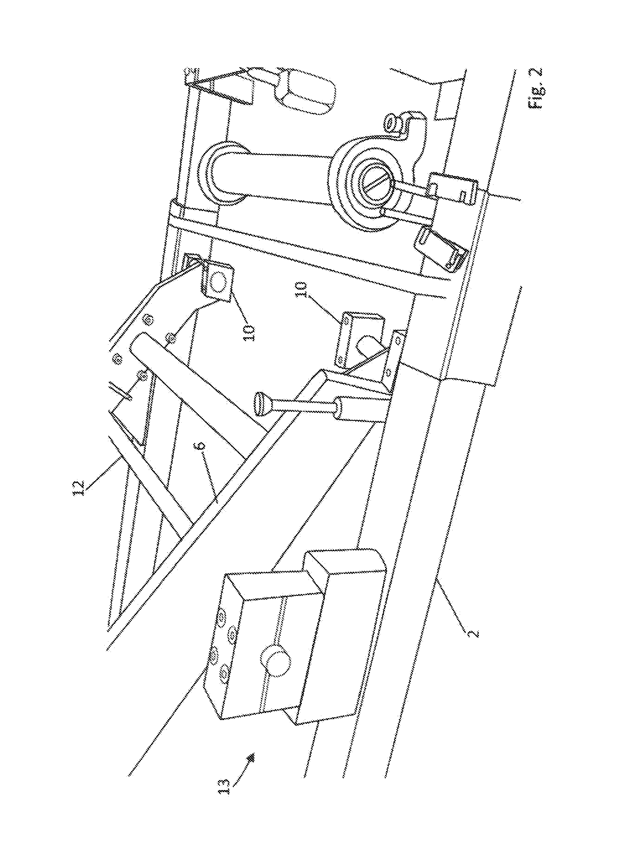
[0024]The first scissor part 6 is attached to the first base element 2 with fixed bearings 10. The second scissor part 3 is attached to the first base element 2 with floating bearings 11.

[0025]To make it possible to change the floating bearing, the first scissor part 6 may be pivotably fixed relative to the first base element 2 a...


PUM

PropertyMeasurementUnit
Distanceaaaaaaaaaa

Abstract

A scissor lift table (1) has a first base element (2) and a second base element (3) and a scissor (4). The scissor (4) has a first scissor part (6) and a second scissor part (7), wherein the first scissor part (6) and the second scissor part (7) are pivotable relative to one another about a scissor axis (5). The first base element (2) and the second base element (3) are connected by the scissor (4) such that a pivoting of the scissor parts (6, 7) relative to one another about the scissor axis (5) causes a change in the distance between the first base element (2) and the second base element (3), wherein the first scissor part (6) is pivotably borne on the first base element (2) using a fixed bearing (10) and the second scissor part (7) is displaceably and pivotably borne on the first base element (2) using a floating bearing (11). The scissor lift table (1) is designed such the first scissor part (6) may be pivotably fixed relative to the first base element (2) about a temporary pivot axis (12) and a mechanical connection (14) between fixed bearing (10) and first base element (2) may be disconnected and the position of the pivot axis is selected such that when the first scissor part (6) is fixed and the mechanical connection (14) is disconnected, reducing the distance between the first base element (2) and second base element (3) causes an increase in the distance between the first base element (2) and the fixed bearing (10).

Description

STATEMENT OF RELATED APPLICATIONS[0001]This patent application claims the benefit of and priority on German Patent Application No. 10 2014 017 844.7 having a filing date of 3 Dec. 2014BACKGROUND OF THE INVENTION[0002]1. Technical Field[0003]The invention relates to a scissor lift table, a scissor lift table system, and a method for changing a fixed bearing of a scissor lift table.[0004]2. Prior Art[0005]Scissor lift tables of the type in question have a first base element and a second base element. These base elements may be frames or platforms, wherein normally one base element is a foundation for the lift table, while the other base element is intended for supporting the load to be lifted by the lift table.[0006]The two base elements are connected to one another by a scissor. The scissor has two scissor parts that are pivotable relative to one another about a scissor axis. The first scissor part is pivotably borne on the first base element using a fixed bearing, while the second s...

Claims


Application Information

Patent Timeline
IPC IPC(8): B66F7/06B66F3/22
CPCB66F3/22B66F7/065B66F7/0641B66F7/28B66F7/0633B66F7/0658
Inventor MOHR, CHRISTOPH
Owner MOHR CHRISTOPH
Why Eureka
Try Eureka