Coupling device for connecting a clutch to a turbine train

Active Publication Date: 2017-02-09
SIEMENS ENERGY GLOBAL GMBH & CO KG
View PDF2 Cites 0 Cited by
  • Summary
  • Abstract
  • Description
  • Claims
  • Application Information

AI Technical Summary

Benefits of technology

[0008]One advantageous refinement consists in an axial stop for positioning the connecting element being formed on the turbine- or generator-side coupling flange. This makes it possible to simply and reproducibly ensure the position of the bolt, in particular during assembly, with respect to the two coupling flanges, without the need for an axial screw connection. In that context, it is particularly advantageous if the axial stop is integrated into a bore in the coupling flange, for example as a stepped bore, such that no additional machining of either of the two coupling flanges is necessary.
[0009]Another advantageous refinement consists in the connecting element being embodied as an expansion bolt with an internal expansion mechanism. An embodiment as an expansion bolt allows the connecting element to be used both for centering the two coupling flanges with respect to one another and for a play-free and form-fitting connection for the purpose of torque transmission. In order to establish an optimum form fit between the expansion bolt and the coupling flange, it is advantageous for the expansion bolt to have a sleeve with a conical internal face and a bolt with a conical external face. Conical faces on

Problems solved by technology

This means that the coupling connection has a certain amount of play with respect to the clutch and the circular motion of the turbine train cannot be reproduced and is negatively influenced.
Since the in

Method used


Image

  • Coupling device for connecting a clutch to a turbine train
  • Coupling device for connecting a clutch to a turbine train
  • Coupling device for connecting a clutch to a turbine train

Examples


Embodiment Construction

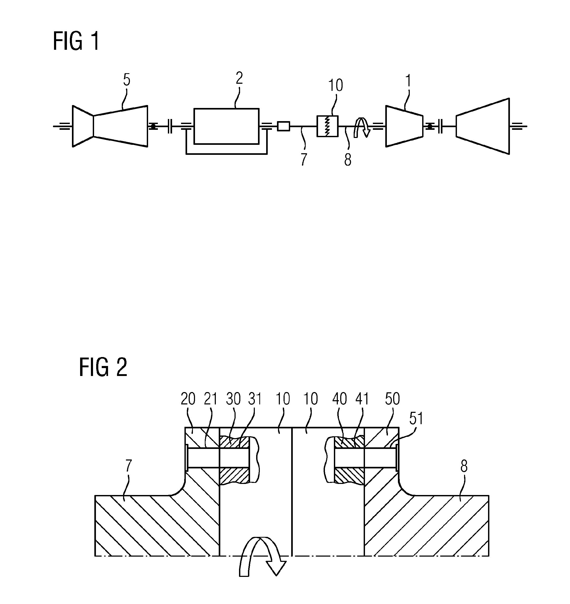
[0017]FIG. 1 shows a turbine train. The turbine train comprises a steam turbine 1, a gas turbine 5 and a generator 2, wherein the generator 2 is also coupled to the steam turbine 1 via a clutch 10. For coupling the clutch, coupling flanges 20, 50 are formed on a generator shaft 7 that connects the clutch 10 to the generator 2 and on a turbine shaft 8 that connects the clutch 10 to a turbine 1, 5, in particular to the steam turbine 5.

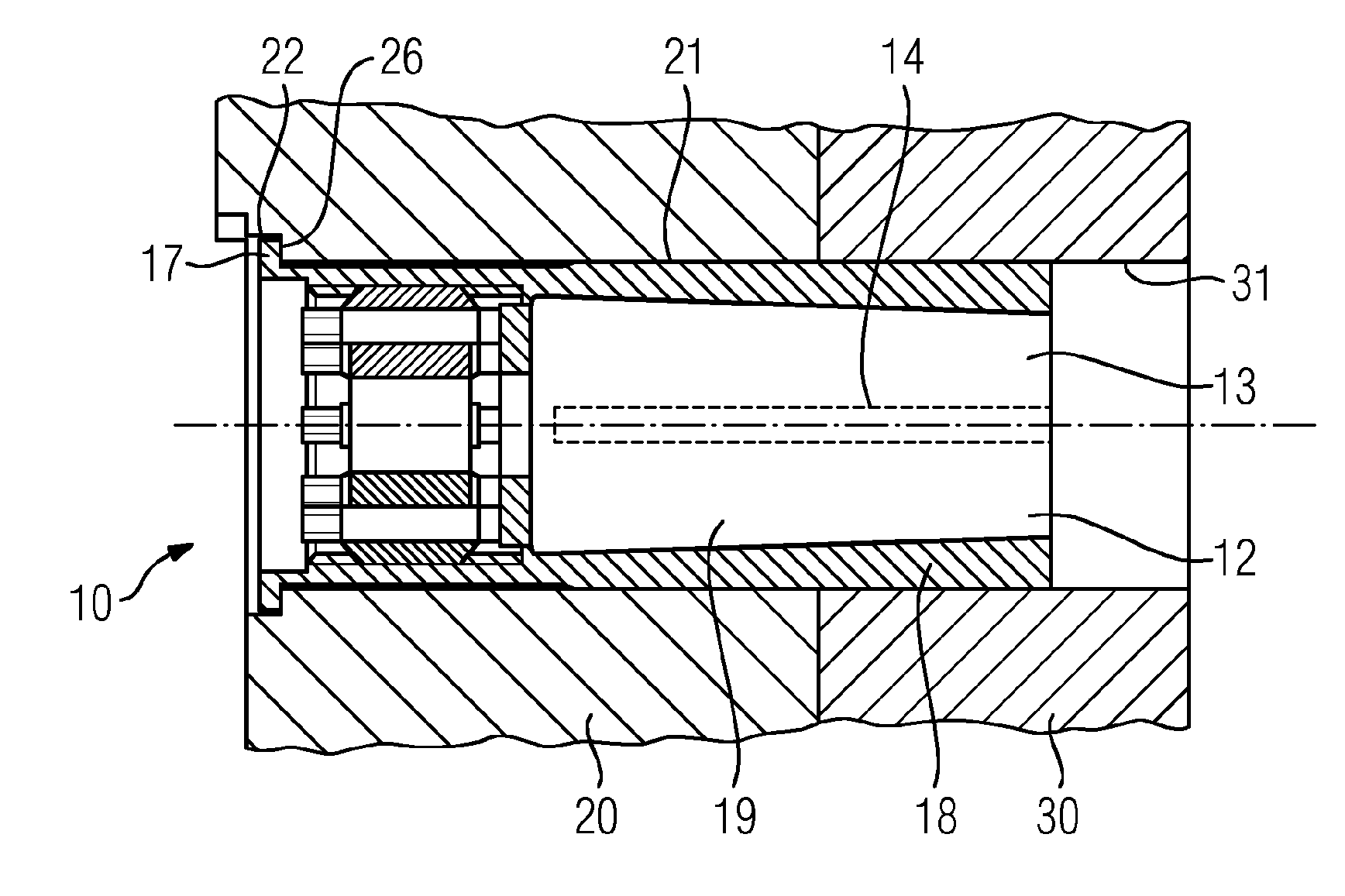
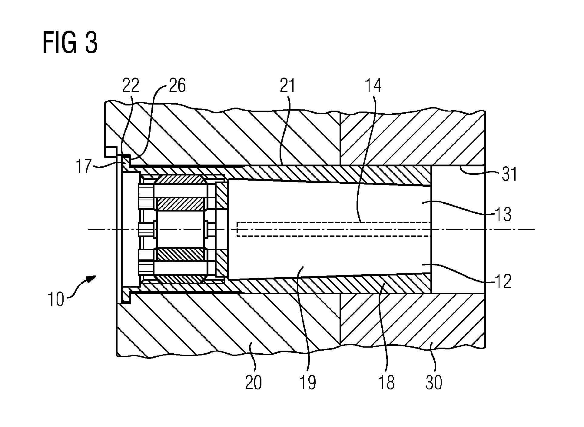
[0018]FIG. 2 shows a coupling device according to the invention for connecting a generator 2 or a generator shaft 7. The coupling device comprises a first coupling flange 20 that is formed on the generator shaft 7 and a second coupling flange 50 that is formed on the turbine shaft 8. The two coupling flanges 20, 50 each have through-bores 21, 51. The clutch 10 has an internal coupling flange 30, 40 at each of its two ends. The internal coupling flanges 30, 40 of the clutch 10 each have blind bores 31, 41. The clutch 10 can be connected to the shafts 7, 8...


PUM


Abstract

A coupling device for connecting a clutch to a turbine train, a turbine train having a clutch, and a method for connecting a clutch to a generator and to a turbine. The coupling device for connecting the clutch has a first coupling flange and a second coupling flange, wherein the first coupling flange and the second coupling flange each have at least one bore for accommodating a coupling bolt. The first coupling flange and the second coupling flange are centered in relation to each other by means of at least one coupling bolt, which is inserted into the bores in the first and in the second coupling flange.

Description

CROSS REFERENCE TO RELATED APPLICATIONS[0001]This application is the US National Stage of International Application No. PCT / EP2015 / 056384 filed Mar. 25, 2015, and claims the benefit thereof. The International Application claims the benefit of European Application No. EP14164721 filed Apr. 15, 2014. All of the applications are incorporated by reference herein in their entirety.FIELD OF INVENTION[0002]The present invention relates to a coupling device for connecting a clutch to a turbine train, to a turbine train having a clutch and to a method for connecting a clutch to a generator and to a turbine.BACKGROUND OF INVENTION[0003]In order to couple a steam turbine to a generator with a gas turbine in a single-shaft plant, use is made of a clutch by means of which, during operation, the steam turbine can be coupled—directly or indirectly by means of an intermediate shaft—to the generator with the connected gas turbine. Such a clutch is known from the prior art. In the case of clutches of...

Claims


Application Information

Patent Timeline
IPC IPC(8): F16D1/076F01D15/10H02K7/18F01D5/02
CPCF16D1/076F01D5/02F05D2260/4023H02K7/1823F01D15/10
Inventor LACOMBE, BERNDMYSCHI, OLIVERPIEPER, DANIEL
Owner SIEMENS ENERGY GLOBAL GMBH & CO KG
Why Eureka
Try Eureka