Resistance furnace with tubular heating element

Inactive Publication Date: 2006-02-28
HERAEUS QUARZGLAS
View PDF9 Cites 0 Cited by
  • Summary
  • Abstract
  • Description
  • Claims
  • Application Information

AI Technical Summary

Benefits of technology

[0031]In this respect it has been found to be of particular advantage when the gas outlets are formed in a flush ring which is arranged above the upper annular collar and is composed of at least two, preferably at least four, separate circular segments, the secondary lines each terminating in one of the circular segments. Four circular segments are obtained when the gas inlet is branched twice into first two and then four secondary lines. The secondary lines preferably terminate mid-way in a respective one of the circular segments, resulting in a further branching of the gas flow. The segments forming the flush ring are positioned on the above-mentioned envelope circle. The gas pressure applied in front of the gas outlets within the circular segments is substantially identical; because of the branches, this is due to the fact that the flush gas covers approximately the same distance from the gas inlet to the gas outlets. A preferred development of the resistance furnace according to the invention is characterized in that the heating element is surrounded by a protective jacket of a controllable temperature whose outer wall has detachably secured thereto cooling pla

Problems solved by technology

The relatively low conductivity of the heat conductor materials and the accompanying voltage drop make it difficult to produce and maintain a homogeneous temperature profile.
It is however very complicated to produce the known heating tube.
Due to its filigree shape it is prone to mechanical damage and must therefore be replaced frequently.
Moreover, due to scaling and oxidation in the region of the supply terminals there might be a deterioration of the electrical

Method used


Image

  • Resistance furnace with tubular heating element
  • Resistance furnace with tubular heating element
  • Resistance furnace with tubular heating element

Examples


Example

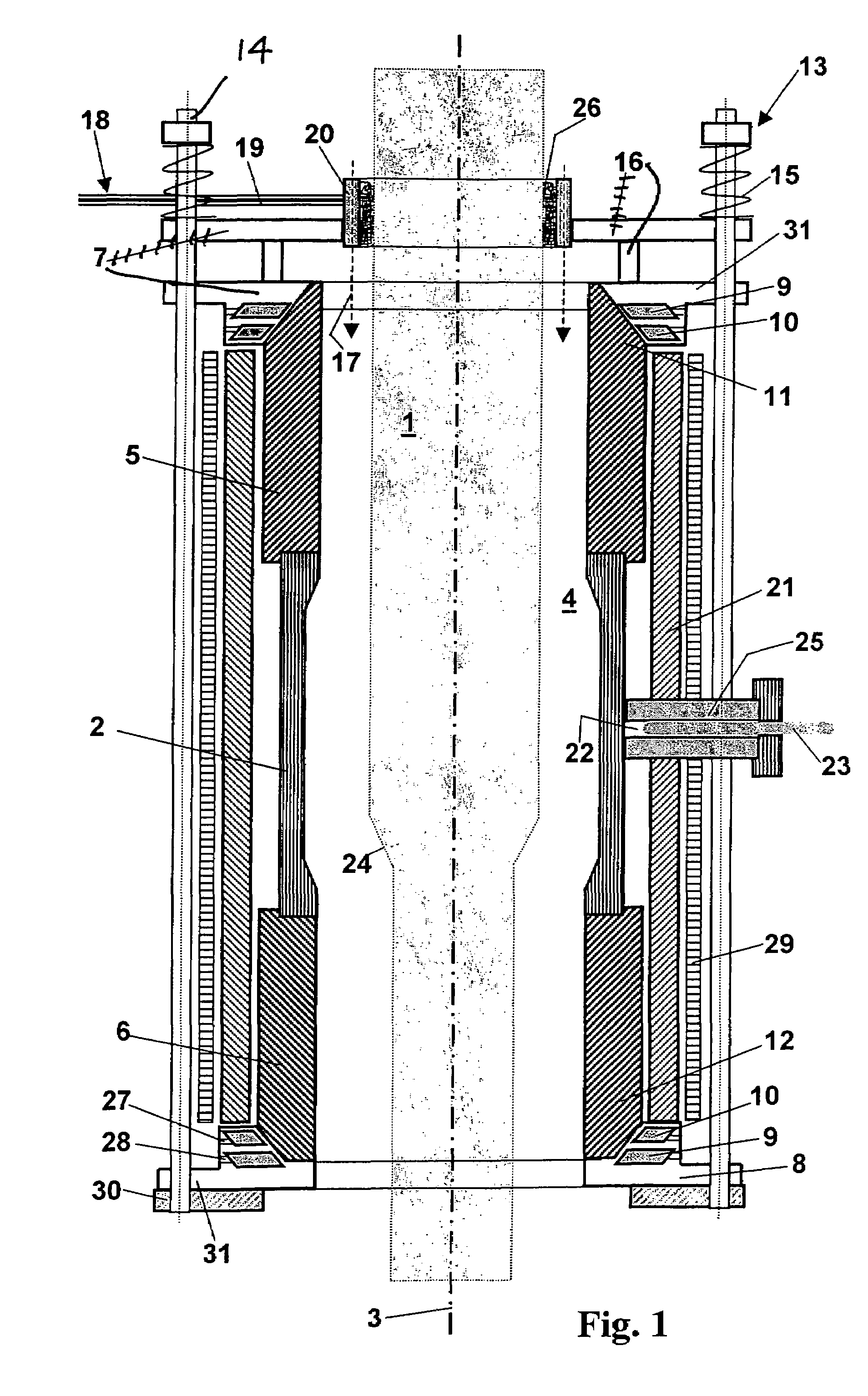
[0038]The resistance furnace according to the invention as shown in FIG. 1 is used for heating and elongating a cylinder 1 of quartz glass. This furnace is a high-performance furnace having a maximum heating capacity of 700 kW. The resistance furnace comprises a heating tube 2 of graphite with a vertically oriented longitudinal axis 3, the heating tube enclosing a heating chamber 4.

[0039]Contact tubes 5; 6 are positioned on the heating tube 2 at both sides at the front. The contact tubes 5; 6 are also made from graphite and have a greater wall thickness than the heating tube 2.

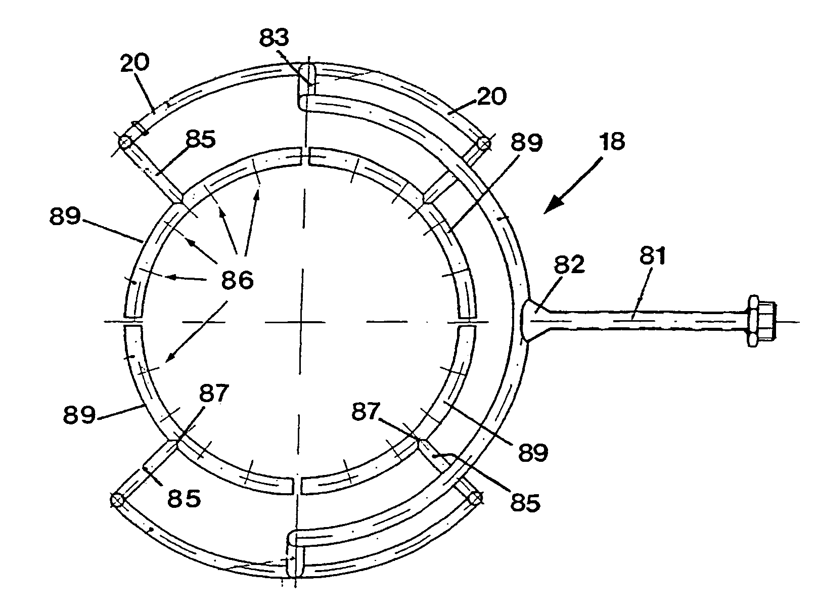
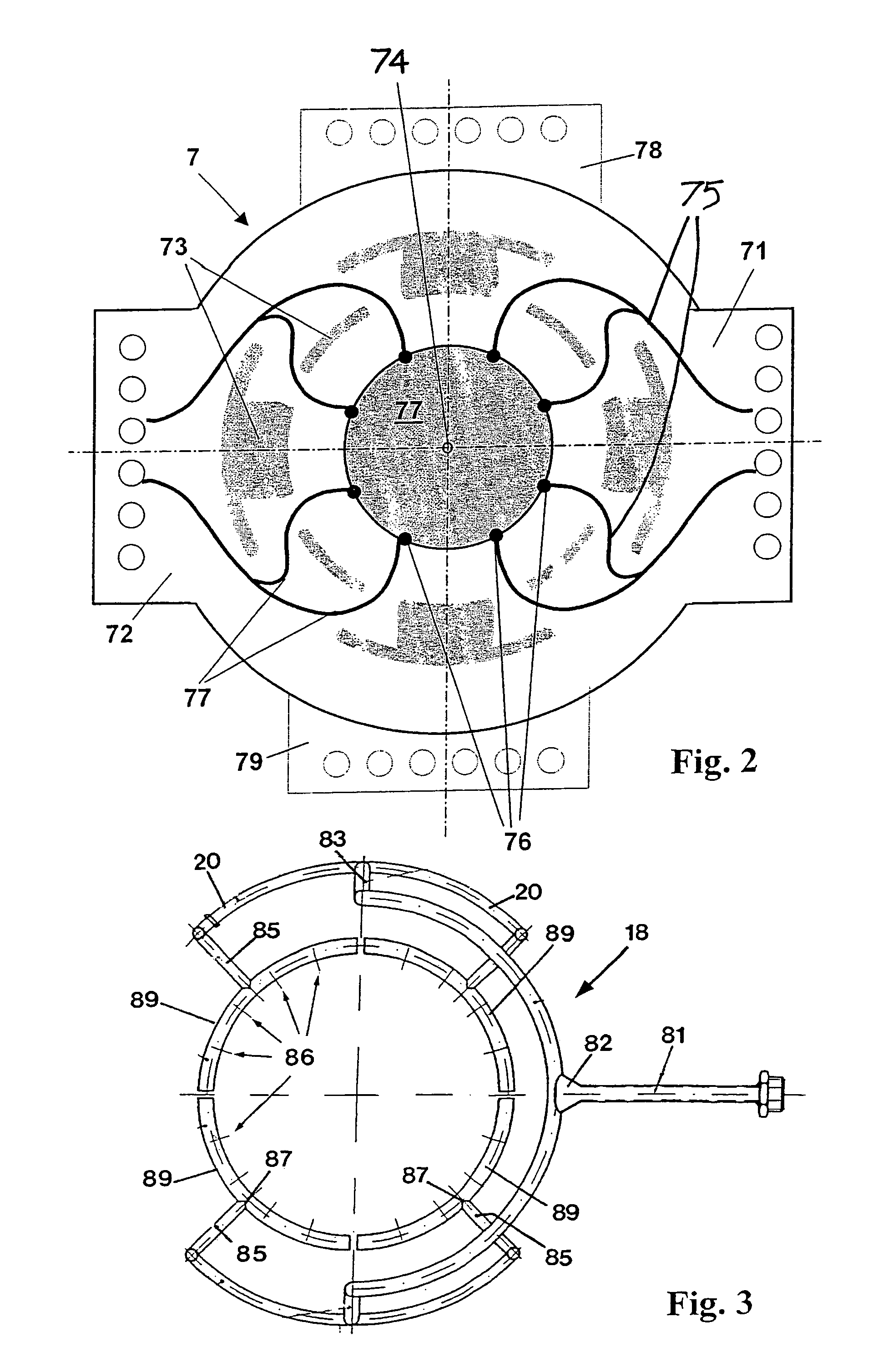
[0040]Heating current is introduced into the heating tube 2 via annular collars 7; 8 consisting of a copper alloy CuCrZr, an upper annular collar 7 resting on the upper side 11 of the upper contact tube 5 and a lower annular collar 8 on the lower side 12 of the lower contact tube 6. The annular collars 7; 8 comprise outwardly projecting flanges 31 which have provided therein through holes each extending radial...


PUM

PropertyMeasurementUnit
Temperatureaaaaaaaaaa
Thicknessaaaaaaaaaa
Pressureaaaaaaaaaa

Abstract

A resistance furnace has a tubular heating element with a vertically-oriented longitudinal axis. The heating element has a shell surface defined by an upper side and a lower side and surrounding a furnace chamber. The heating element is connected to at least two supply terminals by which heating current is introduced at power supply points into the heating element. The supply terminals include a surrounding upper annular collar adjacent the upper side of the shell surface, and also a surrounding lower annular collar adjacent the lower side of the shell surface.

Description

FIELD OF THE INVENTION[0001]The present invention relates to a resistance furnace comprising a tubular heating element having a vertically oriented longitudinal axis, the element comprising a shell surface defined by an upper side and a lower side and surrounding a furnace chamber, and the element being connected to supply terminals by means of which heating current is introduced into the heating element at power supply points.BACKGROUND OF THE INVENTION[0002]High temperatures can be achieved with the help of resistance furnaces. Electrical current flows through an ohmic resistor designed as a heat conductor, the electrical power being mainly converted into heat. Metal, such as molybdenum, tantalum, and platinum, ceramics, SiC, or modifications of carbon, such as coal, graphite or vitreous carbon (pyrolytically produced carbon) are suited as a material for the heat conductor. Heat conductors of graphite are characterized by their high temperature resistance, simple shape and low pri...

Claims


Application Information

Patent Timeline
IPC IPC(8): F27D7/06H05B3/02F27B9/28F27B17/00F27D7/02F27D9/00F27D11/02F27D19/00F27D21/00F27D99/00H01L21/00H05B3/62
CPCF27B17/00F27D11/02F27D21/0014C03B23/043H01L21/67109H05B3/62C03B37/01257F27B9/28F27D7/02F27D7/06F27D2009/0045F27D2019/0025F27D2099/001F27D99/0073
Inventor BOGDAHN, THOMASGANZ, OLIVER
Owner HERAEUS QUARZGLAS
Why Eureka
Try Eureka