Bearing structure

Active Publication Date: 2016-06-09
ROLLS ROYCE PLC
View PDF11 Cites 2 Cited by
  • Summary
  • Abstract
  • Description
  • Claims
  • Application Information

AI Technical Summary

Benefits of technology

[0025]In some embodiments, the first and second compliant element (e.g. first and second diaphragm) may be slidably mounted to the housing. For example, the housing may comprise a first groove for locating the radially outer end of the first compliant element. The housing may comprise a second g

Problems solved by technology

Thrust loads arise in a gas turbine engine as the result of pressure imbalances.
The thrust loads urging the compressor upstream and the compressor downstream are high and uncertain.
Since single thrust bearings inevitably have a limited thrust capability, two or more bearings may be arranged adjacent one another to share the thrust load.
Furthermore, under-loading of one set of rolling elements may result in “skidding” of that set, which may cause damage, debris release and bearing failure.
This requirement to precision-engineer and match bearings in pairs (or other multip

Method used


Image

  • Bearing structure
  • Bearing structure
  • Bearing structure

Examples


Example

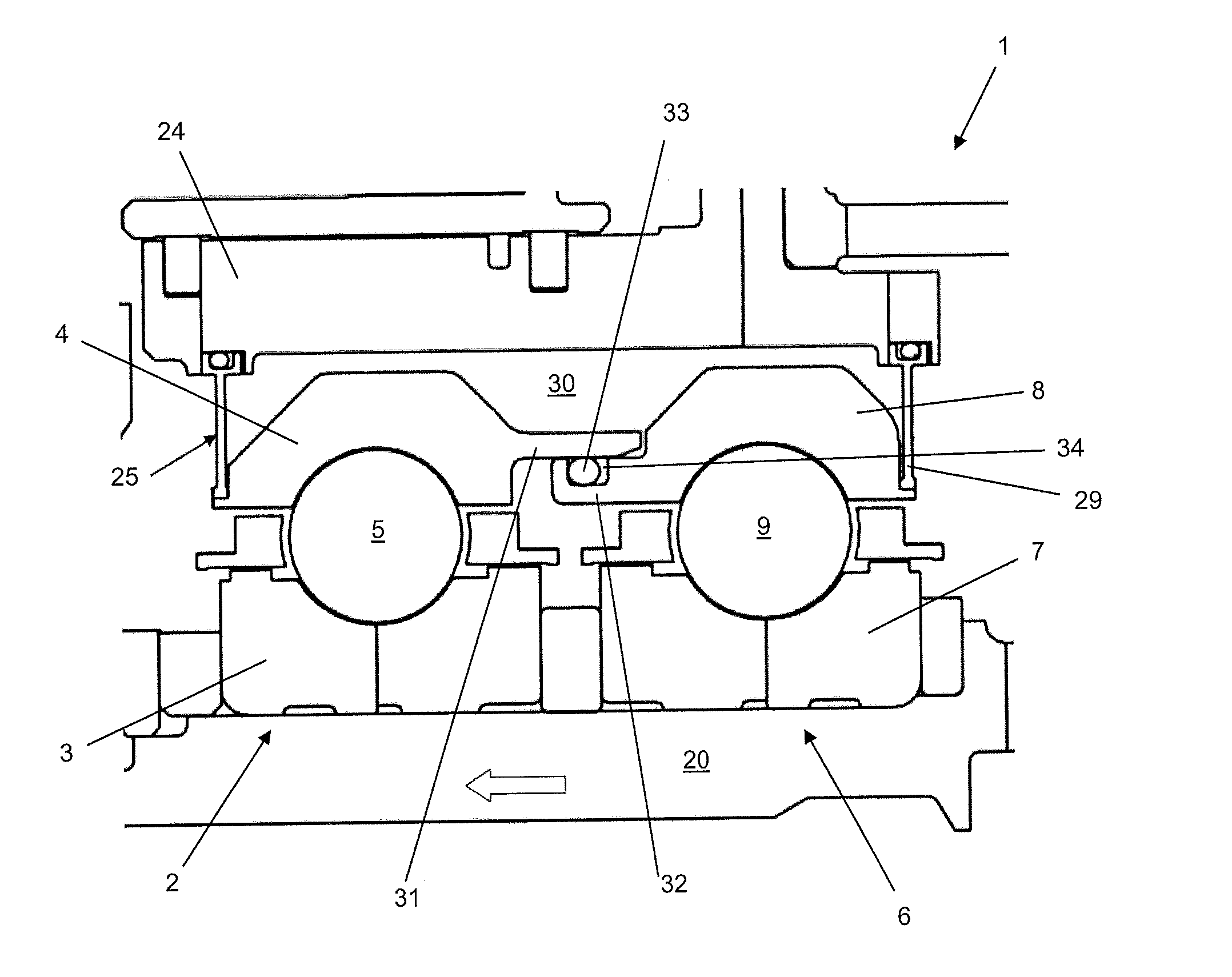
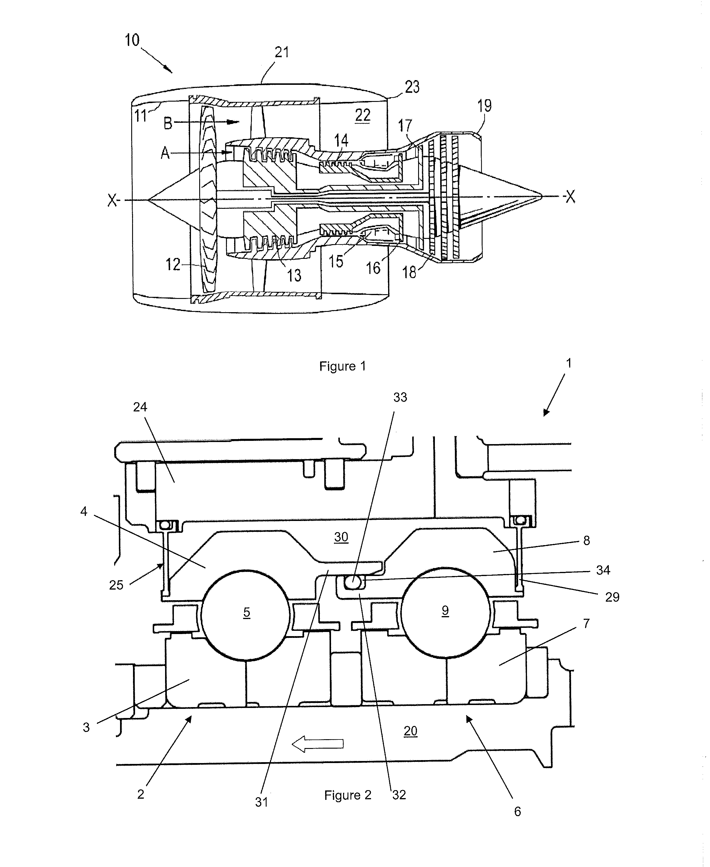
[0040]FIG. 2 shows a first embodiment of a stacked bearing structure according to various examples;

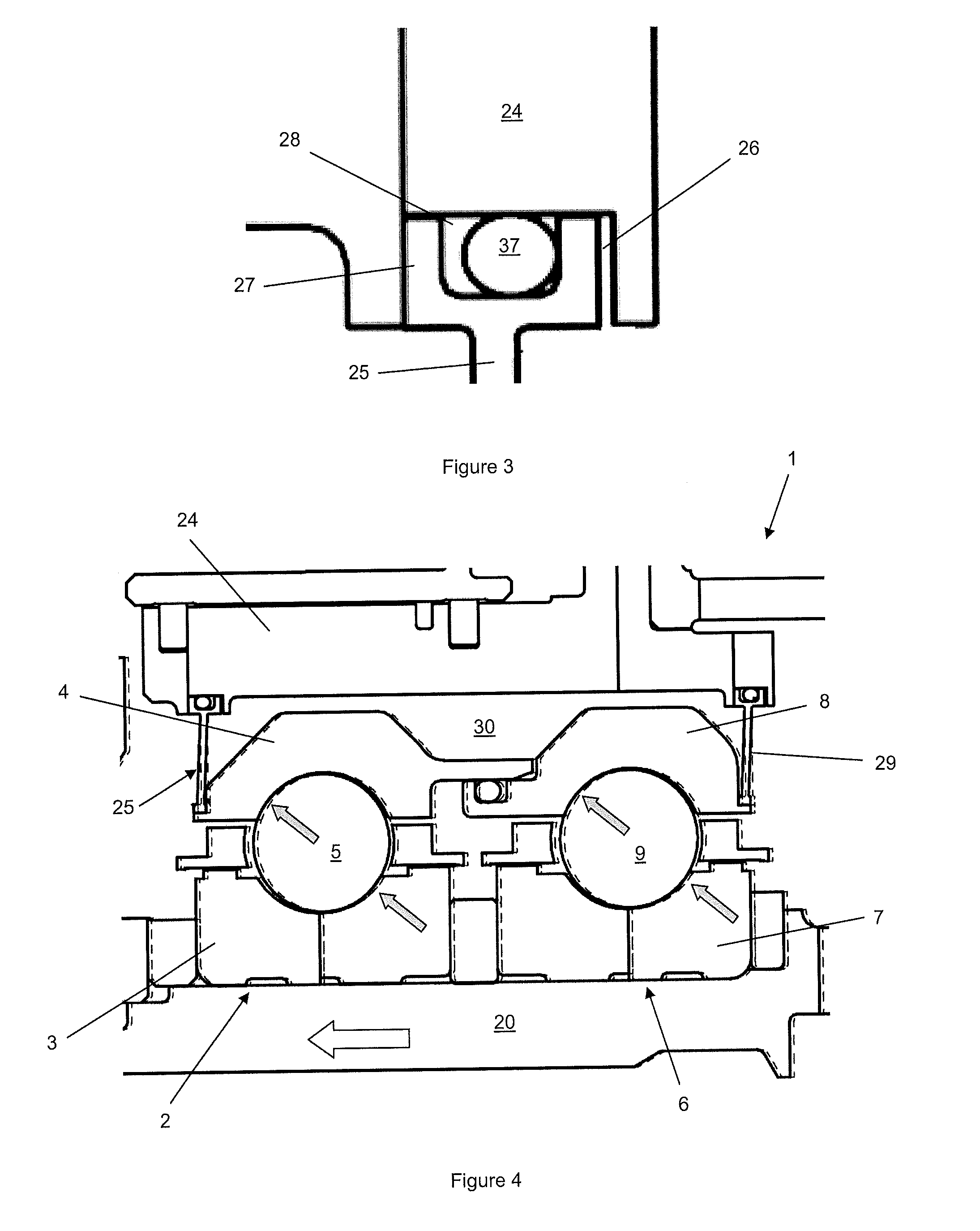
[0041]FIG. 3 shows a sliding join between components of the first embodiment;

[0042]FIGS. 4-7 show the first embodiment in various operational situations;

Example

[0043]FIG. 8 shows a second embodiment of a stacked bearing structure according to various examples; and

[0044]FIG. 9 illustrates a schematic of the ECU and logical connections to the load sensors and valved pressure inlet / outlets.

DETAILED DESCRIPTION

[0045]With reference to FIG. 1, a ducted fan gas turbine engine incorporating one or more stacked bearing structures is generally indicated at 10 and has a principal and rotational axis X-X. The engine comprises, in axial flow series, an air intake 11, a propulsive fan 12, an intermediate pressure compressor 13, a high-pressure compressor 14, combustion equipment 15, a high-pressure turbine 16, an intermediate pressure turbine 17, a low-pressure turbine 18 and a core engine exhaust nozzle 19. A nacelle 21 generally surrounds the engine 10 and defines the intake 11, a bypass duct 22 and a bypass exhaust nozzle 23.

[0046]During operation, air entering the intake 11 is accelerated by the fan 12 to produce two air flows: a first air flow A in...


PUM


Abstract

Load sharing stacked bearing structure including first bearing having a first inner race, first outer race and first set of roller elements housed between first inner race and first outer race and a second bearing having a second inner race, second outer race and second set of roller elements housed between second inner race and the second outer race. A housing surrounds the first and second bearings. First compliant element is provided with the first compliant element connected between the housing and the first outer race. The first compliant element, first outer race and housing define at a pressure chamber. The first outer race axially slidable relative to the second outer race such that an increase in pressure in pressure chamber causes a change in axial spacing between the outer races. This induces an additional axial load on the bearings which helps balance thrust load sharing.

Description

TECHNOLOGICAL FIELD[0001]The present disclosure relates to a bearing arrangement and a gas turbine engine having such a bearing arrangement.BACKGROUND[0002]In gas turbine engines, one or more rotors of the engine can be subjected to axial thrust loads during operation. Thrust loads arise in a gas turbine engine as the result of pressure imbalances. For example, a compressor has a higher downstream pressure than upstream pressure which forces the compressor upstream (towards the intake) whereas a turbine has a higher upstream pressure than downstream pressure which forces the turbine downstream (towards the exhaust nozzle). The thrust loads urging the compressor upstream and the compressor downstream are high and uncertain.[0003]The thrust loads are often at their maximum during the periods of highest power output for the engine. In a gas turbine engine providing jet propulsion for an aircraft, this period of maximized power output can occur when the aircraft is taking-off and / or cli...

Claims


Application Information

Patent Timeline
IPC IPC(8): F16C19/54F01D25/16F16C19/52F16C19/06F16C33/78F16C35/04
CPCF16C19/54F16C33/7823F16C35/042F05D2220/32F16C19/06F01D25/16F05D2240/54F16C19/522F16C41/02F16C19/16F02C7/06F16C25/08F01D25/164F05D2260/15F16C2360/23F16C19/542
Inventor GALLIMORE, STEPHENFLETCHER, PAULPETERS, PHILIP
Owner ROLLS ROYCE PLC
Why Eureka
Try Eureka