Methods and systems for preventing bleeding from the left atrial appendage

a technology of atrial appendage and preventing bleeding, applied in the field of medical devices and medical methods, can solve the problems of insufficient circulatory ex watchman device is the incomplete occlusion of the laa, and gaps are more likely to enlarge, so as to improve the adhesion of the balloon surface, prevent the dislodging of circumferential tie or constriction, and increase the effectiveness of preventing bleeding

Active Publication Date: 2016-06-16
KRISHNAN SUBRAMANIAM CHITOOR
View PDF2 Cites 14 Cited by
  • Summary
  • Abstract
  • Description
  • Claims
  • Application Information

AI Technical Summary

Benefits of technology

[0064]In another exemplary embodiment, a method of the present disclosure further comprises the following features. For brevity, steps (1)-(20) of the exemplary embodiment of the present disclosure's method are incorporated herein. At step (7), the third inflatable balloon has caliber tubes attached to its exterior. These tubes will allow for the application of vacuum or suction forces to the left atrial tissue or to the surface of the adjacent balloon to provide for a tighter hemostatic seal.
[0073]In another exemplary embodiment, a method of the present disclosure comprises the following features. The wall of the LAA tends to be extremely thin. While attempting to pierce this wall, the wall may invaginate (seen as a dashed line in FIG. 24). The subsequent puncture may therefore, may occur in an oblique fashion and may result in a tear or a laceration rather than as a focused and sharply limited perforation. In order to pierce the wall optimally, it is critical to hold it fixed and prevent invagination during piercing of the structure (the taut and fixed LAA wall is shown as 2504 in FIG. 27A). FIG. 25 shows a suction cannula that applies suction to the LAA wall with a piercing element that is within the suction cannula. In this exemplary embodiment, it is preferable that perforation of the structure occur perpendicular to the left atrial wall rather than in an oblique manner. However, the design shown in FIG. 25 may be problematic. The thin wall of the appendage may get sucked into the cannula in the form or a nipple, bleb or bubble. The wall may get pierced in an oblique and suboptimal fashion. To facilitate a focused puncture rather than a tear or a laceration, the piercing element will inserted through a tube and attached to the circumference of this outer tube, will be a plurality of suction elements (shown in FIGS. 27A-C) which will keep the LAA wall taut (2504 in FIG. 27A) and prevent it from getting sucked into the tube that houses the piercing element. In a preferred embodiment, no suction will be applied through the main lumen of the tube (2708) via which the piercing element (2102) is advanced. It is also expected that the surface of the balloon upon inflation within the LAA (seen as 2802 in FIGS. 28; 2904 and 2906 in FIG. 29; and as 3002 in FIG. 30) will have tubes attached to it to apply suction.
[0077]With epicardial surgical cannulation of the LA appendage and a subsequent inflation of a balloon within the LA appendage, a system of multiple balloons or expanding elements that adhere to each other with one balloon inflated within the left atrial cavity (and thus trying to achieve a tight seal across the ostium of the appendage) may not be necessary. This is because since the operator has ready access to the pericardial cavity and epicardial surface of the left atrium appendage, after inflating the balloon, pressure can be applied with a constricting device or loop from the epicardial surface. Or, “counter-pressure” can be applied in a circumferential manner from an outer sheath. The term counter-pressure refers to pressure applied in one direction to counter balance pressure from another. Hence, the wall of the left atrial appendage may be compressed in a circumferential manner from both the endocardial and epicardial directions. The endocardial pressure will be applied by the inflated balloon that after inflation, is pulled backwards towards the point of entry (shown in FIGS. 28 and 29). FIG. 28 illustrates an embodiment of the present disclosure in which an inflatable balloon 2802 is inflated within a cavity of the LAA 2406. The inflatable balloon 2802, upon inflation and pulling back towards the entry point, may apply pressure against an interior or endocardial surface of the LAA. The pressure applied by the inflatable balloon 2802 may be applied in a direction towards the exterior of the LAA. Similarly, in FIG. 29, the balloon that has a strawberry shape (2904 and 2906) is inflated and is pulled back towards the entry point. The pressure applied by the inflatable balloon may be provided by the pressure of inflation, or may be provided by a force caused by the sheath 2804 being drawn in a direction towards the exterior of the LAA. A pressure applicator device that applies pressure on the outer or epicardial surface is shown as 2808 in FIG. 28 and as 2908 in FIG. 29. The epicardial pressure applicator may be used to apply pressure to the LAA in a direction opposite to the pressure applied by the inflatable balloons. The pressure applicator device 2808 may be pushed towards the LAA wall. The pressure applicator device 2808 may comprise a sleeve or other form of pressure applicator device that is configured to apply pressure to the outer surface of the LAA. In the embodiment shown in FIG. 28, the pressure applicator device 2808 may have a funnel shape configured to contour to the shape of the LAA. The funnel shape may increase the area over which pressure is applied. In one embodiment, the pressure applicator device, and / or the inflatable balloon may have shapes that complement each other as shown in FIG. 29. For example, in one embodiment, the inflatable balloon may have a conical shape and the pressure applicator device may have a funnel shape.
[0079]The pressures applied by the inflatable balloon 2802 and the pressure applicator device 2802 may comprise counter-pressures. The pressures are applied in opposite directions and thus counter balance each other. The compressive force may serve to seal the LAA ostium, and / or prevent bleeding from the wall of the LAA.
[0081]The pressure applicator device 2908 in FIG. 29 may have a funnel shape to complement the conical shape of the second portion of the expanding element 2906. The pressure applicator device 2908 may be pressed against the outer surface of the LAA wall, and the inflatable balloon may be inflated to provide a pressure against the inner surface of the LAA wall, or may be drawn towards the inner surface of the LAA wall. An effective counter pressure may be provided in the embodiment of FIG. 29 that is achieved over a larger area than shown in regard to the embodiment of FIG. 28. To increase the effectiveness of preventing bleeding across the entry site, the inflatable balloon may have suction tubes along its inflated surface to improve adhesion of the balloon surface with the endocardial wall of the LAA.
[0082]In another exemplary embodiment, a method of the present disclosure comprises the following features. FIG. 30 shows an example of counter-pressure where the epicardial pressure is exerted circumferentially in a constricting manner along a preselected zone. In this embodiment, epicardial pressure is not exerted around the entry site of the LAA. In this Figure, inflatable balloon 3002 is inflated within a cavity of the LAA 2406. The LAA is entered from a surgically accessed exterior / pericardial space. The inflatable balloon 3002 may be coupled to a sheath 3004. The inflatable balloon 3002 may include an indentation 3006. The indentation 3006 may have the form of a groove that extends circumferentially around the balloon 3002. The indentation 3006 may be pre-formed into the inflatable balloon 3002 and serves to prevent the circumferential tie or constriction from dislodging.

Problems solved by technology

However, the WATCHMAN device's “one size or one shape fits all” approach results in several limitations, such as inadequate circulatory exclusion of the LAA.
For example, a major limitation of the WATCHMAN device is the incomplete occlusion of the LAA because it is relatively common for there to be a gap between the WATCHMAN device surface and the LAA wall.
These gaps are more likely to enlarge over time and persist, while new gaps also occur during follow up.
The long, tortuous and pedunculated structure of the LAA can make it difficult to seat the device within the LAA cavity.
This can result in the device placed in a suboptimal manner with incomplete occlusion, and an incomplete occlusion is worse than no occlusion.
Another limitation of the WATCHMAN device is the fixation of barbs or wires engaged in the walls of the LAA.
Pericardial effusion is the abnormal accumulation of fluid in the pericardial cavity, which can negatively affect heart function.
The procedure of obtaining pericardial access with a needle via a subxiphoid approach can be technically difficult, and associated complications include lacerations of the myocardium, the coronary arteries and veins.
Due to the severe technical limitations associated with the procedure, it has not been adopted in a widespread manner.
LAA ligation from a circumferentially applied suture or tie also suffers from puckering of the occlusion which can compromise sealing.
In addition to causing a puckering and incomplete occlusion of the LAA ostium, a circumferential suture also has the disadvantage of having a potential to cause a tear or laceration of the LAA.
It is anticipated that in the elderly hearts (the elderly patients are the primary candidates of this approach), which are known to be delicate, this approach may be associated with an even greater risk of bleeding and tears.
In the event of a tear of the LAA in the elderly hearts, there is a high likelihood of this being fatal.
Due to these recesses and lobes, a single occlusion member within the LAA cavity is unlikely to provide an effective hemostatic seal.
In particular, at least one of the inflatable balloons occluding the LAA ostium is non-compliant, such that upon inflation of the non-compliant balloon, the surrounding LAA walls are expanded to accentuate the constriction that one would expect at the LAA ostium.
Second, the use of electromagnetic or magnetic coils within the inflatable balloons, wherein upon inflation of these balloons, the electromagnetic or magnetic coils also expand within these balloons, is not present in the prior art.
However, inflating a cylindrical balloon solely within the LAA is unlikely to provide a safe and stable hemostatic occlusive seal for the following reasons.
The presence of these lobes and recesses makes it difficult for a single balloon inflated within the LAA to provide an effective seal since the cavity of the lobes and the recesses would allow for blood through flow through.
Applying a circumferential tie or suture to the LAA ostium is going to compress a fixed circumference to a smaller area and therefore will cause puckering.
Puckering is more likely to cause gaps and incomplete occlusion.
A suture is also more likely to cause tears in the LAA especially in elderly hearts.
The wall of the LAA tends to be extremely thin.
The subsequent puncture may therefore occur in an oblique fashion and may result in a tear or laceration rather than a focused and sharply limited perforation.

Method used


Image

  • Methods and systems for preventing bleeding from the left atrial appendage
  • Methods and systems for preventing bleeding from the left atrial appendage
  • Methods and systems for preventing bleeding from the left atrial appendage

Examples


Embodiment Construction

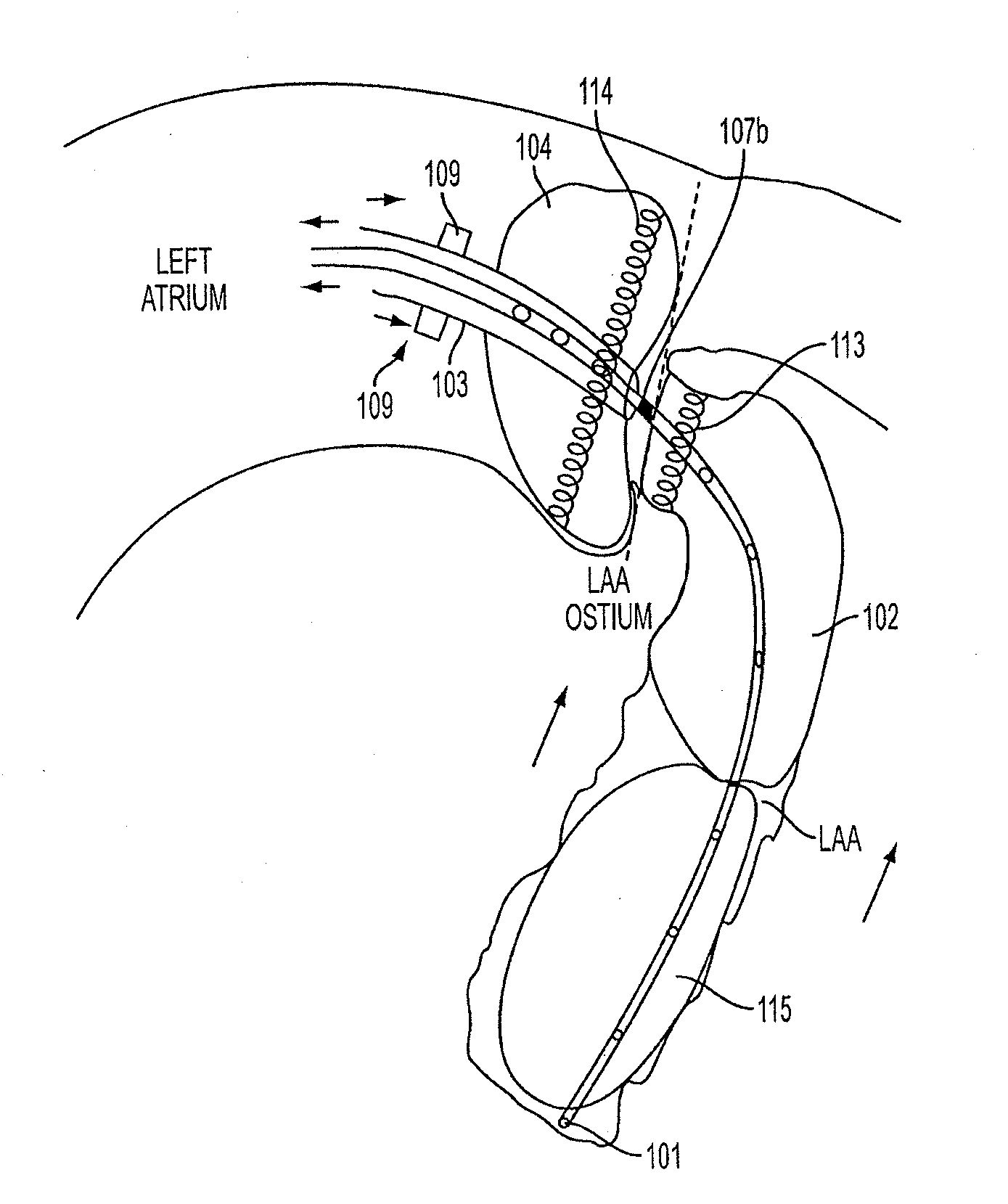
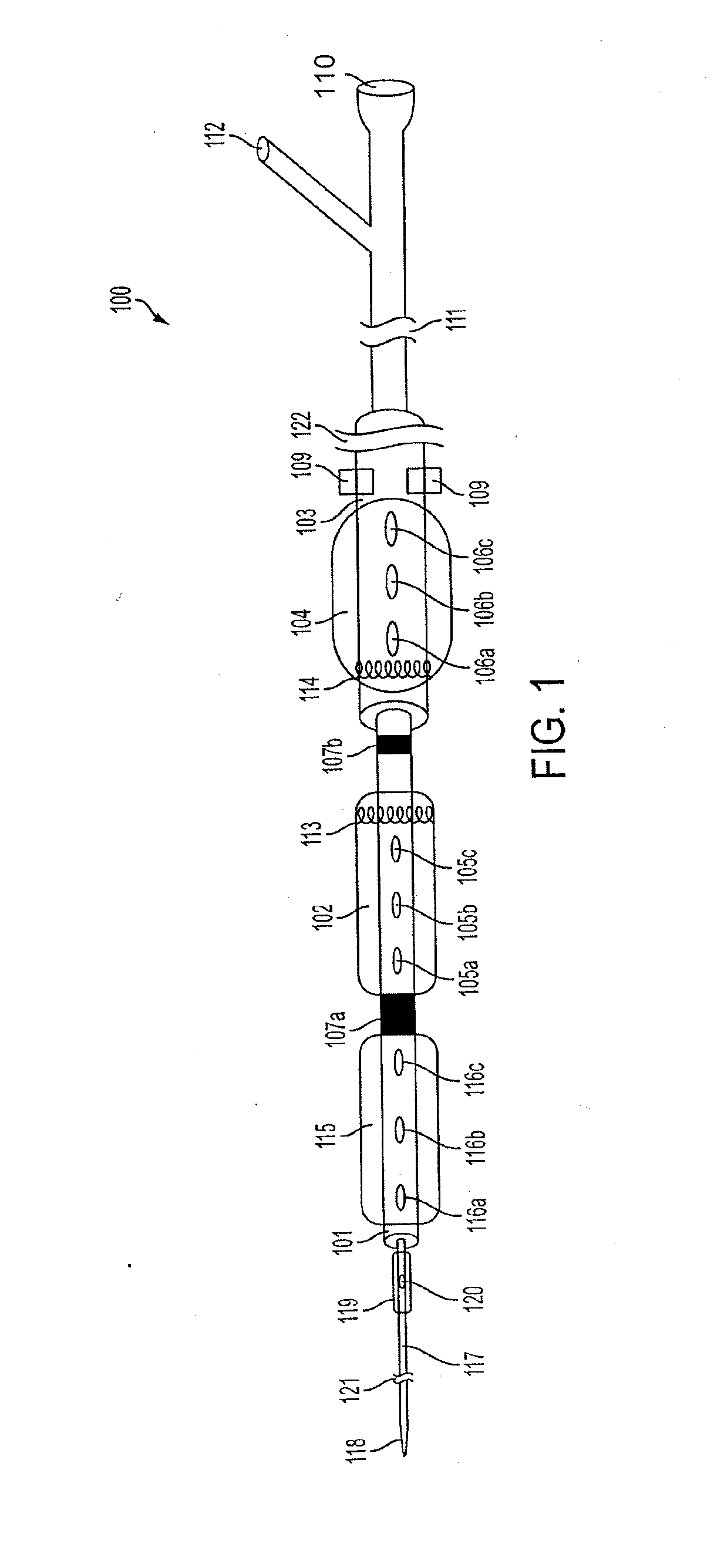
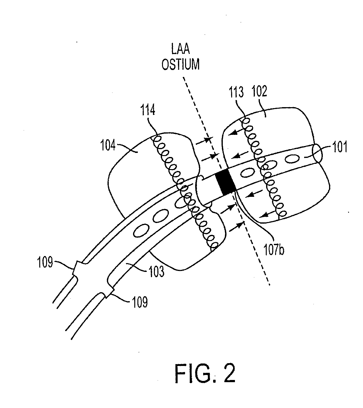
[0124]FIG. 1 is a perspective view of an exemplary embodiment of a catheter 100, which is part of aspects of the present disclosure's system for accessing a pericardial space and preventing strokes arising from the LAA. The present disclosure's system also includes closure device 1300, as shown in the exemplary embodiment of FIG. 13. FIG. 1 shows a stand-alone catheter 100 before it is introduced into a body cavity and thus, FIG. 1 shows inflatable balloons 102, 104, 115 and 119 in their un-inflated form. Inflatable balloon 104 is attached to an outer sheath 103. Inflatable balloons 102 and 115 are attached to inner sheath 101. Inflatable balloon 119 is attached to inner catheter 117. Depending on the desired degree of compliance, inflatable balloons 102, 104, 115 and 119 can be made of rubber, latex, polyisoprene, silicone, polyurethane, or any combination thereof. Rubber, latex, polyisoprene, and silicone produce more compliant inflatable balloons. Polyurethane produces non-compli...


PUM

PropertyMeasurementUnit
suction forceaaaaaaaaaa
pressureaaaaaaaaaa
shapeaaaaaaaaaa

Abstract

The disclosure presents methods and systems for applying a suction force to a surface of a left atrial appendage (LAA) with a plurality of tubes. A method may include puncturing the surface of the LAA using a tissue-penetrating tip while the suction force is applied to the surface. The disclosure also presents methods and systems for inflating a first inflatable balloon within a cavity of a left atrial appendage (LAA). A method may include applying a suction force with at least one tube coupled to the first inflatable balloon to attract the first inflatable balloon to an interior surface of the LAA or to a second inflatable balloon.

Description

CROSS REFERENCE TO RELATED APPLICATIONS[0001]This application is a continuation-in-part of prior U.S. patent application Ser. No. 14 / 941,469, entitled “METHODS AND SYSTEMS FOR ACCESSING A PERICARDIAL SPACE AND PREVENTING STROKES ARISING FROM THE LEFT ATRIAL APPENDAGE,” filed Nov. 13, 2015, which is a continuation of prior U.S. patent application Ser. No. 13 / 973,949, entitled “METHODS AND SYSTEMS FOR ACCESSING A PERICARDIAL SPACE AND PREVENTING STROKES ARISING FROM THE LEFT ATRIAL APPENDAGE,” filed Aug. 22, 2013, which claims the benefit and priority under 35 U.S.C. §119(e) of U.S. Provisional Patent Application No. 61 / 692,171, entitled “METHODS AND SYSTEMS FOR ACCESSING A PERICARDIAL SPACE AND PREVENTING STROKES ARISING FROM THE HEART,” filed on Aug. 22, 2012, the entire contents and disclosures of each of these applications being hereby incorporated by reference herein; this application is also a continuation-in-part of prior U.S. patent application Ser. No. 14 / 941,457, entitled “A...

Claims


Application Information

Patent Timeline
Patent Type & Authority Applications(United States)
IPC IPC(8): A61B17/00A61B17/04A61B34/00A61B17/12
CPCA61B17/0057A61B17/12122A61B17/12136A61B17/0469A61B34/73A61B2017/12127A61B2017/00632A61B2017/00243A61B2017/1205A61B2017/00876A61B2017/306A61B17/12013A61B17/1204A61B17/3478A61B18/02A61B18/0206A61B18/082A61B18/1477A61B18/1492A61B18/20A61B2017/00247A61B2017/00323A61B2017/00566A61B2017/00898A61B2017/0495A61B2017/22069A61B2018/00136A61B2018/0022A61B2018/00261A61B2018/00273A61B2018/00285A61B2018/00291A61B2018/00357A61B2018/00601A61B2018/00613A61B2018/00619A61B2018/046A61N7/022A61B2034/731A61B2090/3966A61B2017/320069A61B2017/32007
Inventor KRISHNAN, SUBRAMANIAM CHITOOR
Owner KRISHNAN SUBRAMANIAM CHITOOR
Why Eureka
Try Eureka