Liquid Ejecting Apparatus

a liquid ejecting and nozzle technology, applied in the direction of printing, other printing apparatus, etc., can solve the problems of increasing the number of components, increasing the pressure in the closed space, and the possibility of air being mixed from the nozzle, so as to suppress the increase in the number of components

Active Publication Date: 2016-06-16
SEIKO EPSON CORP
View PDF0 Cites 22 Cited by
  • Summary
  • Abstract
  • Description
  • Claims
  • Application Information

AI Technical Summary

Benefits of technology

[0007]An advantage of some aspects of the invention is to provide a liquid ejecting apparatus in which it is possible to suppress an increase in the number of components and to detect malfunction of an expendable item.

Problems solved by technology

Therefore, in order to detect clogging of a filter, a dedicated sensor needs to be provided, which results in an increase in the number of components.
Also, when the space, which the nozzle faces, is closed with the moisturizing cap in which the air communicating section insufficiently functions, a pressure in the closed space is increased and air is likely to be mixed from the nozzle.

Method used


Image

  • Liquid Ejecting Apparatus
  • Liquid Ejecting Apparatus
  • Liquid Ejecting Apparatus

Examples


first embodiment

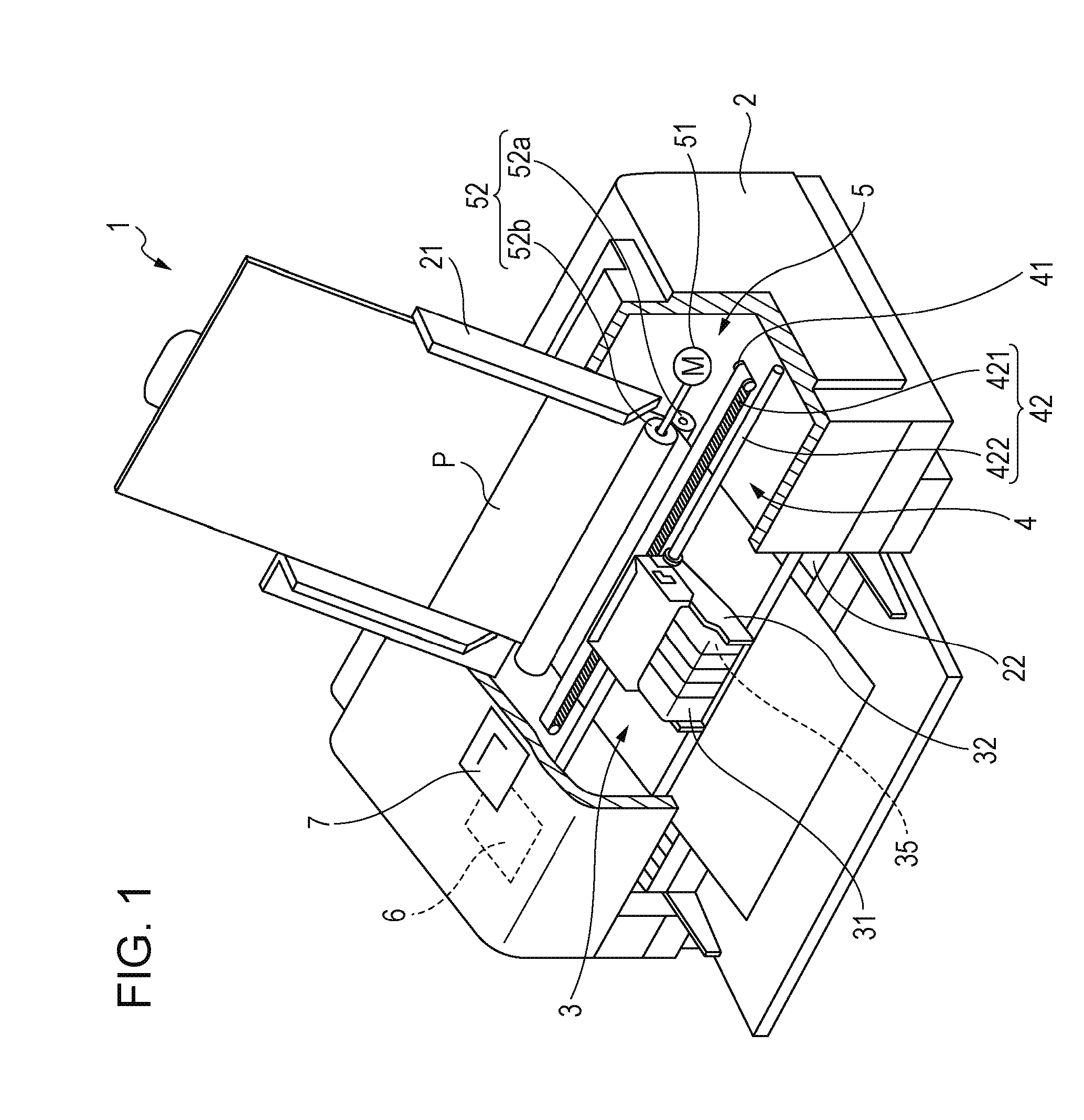
[0096]FIG. 1 is a diagram schematically illustrating a configuration of an ink jet printer 1 which is a kind of a liquid ejecting apparatus according to a first embodiment. Further, in the description below, in FIG. 1, an upper side in a vertical direction is referred to as an “upper portion”, and a lower side in the vertical direction is referred to as a “lower portion”. Firstly, a configuration of the ink jet printer 1 is described.

[0097]The ink jet printer 1 illustrated in FIG. 1 includes an apparatus main body 2, and a tray 21 to which a recording sheet P is installed is provided in the backward upper portion, a paper discharging opening 22 that discharges the recording sheet P is provided in the forward lower portion, and an operation panel 7 is provided on the upper surface.

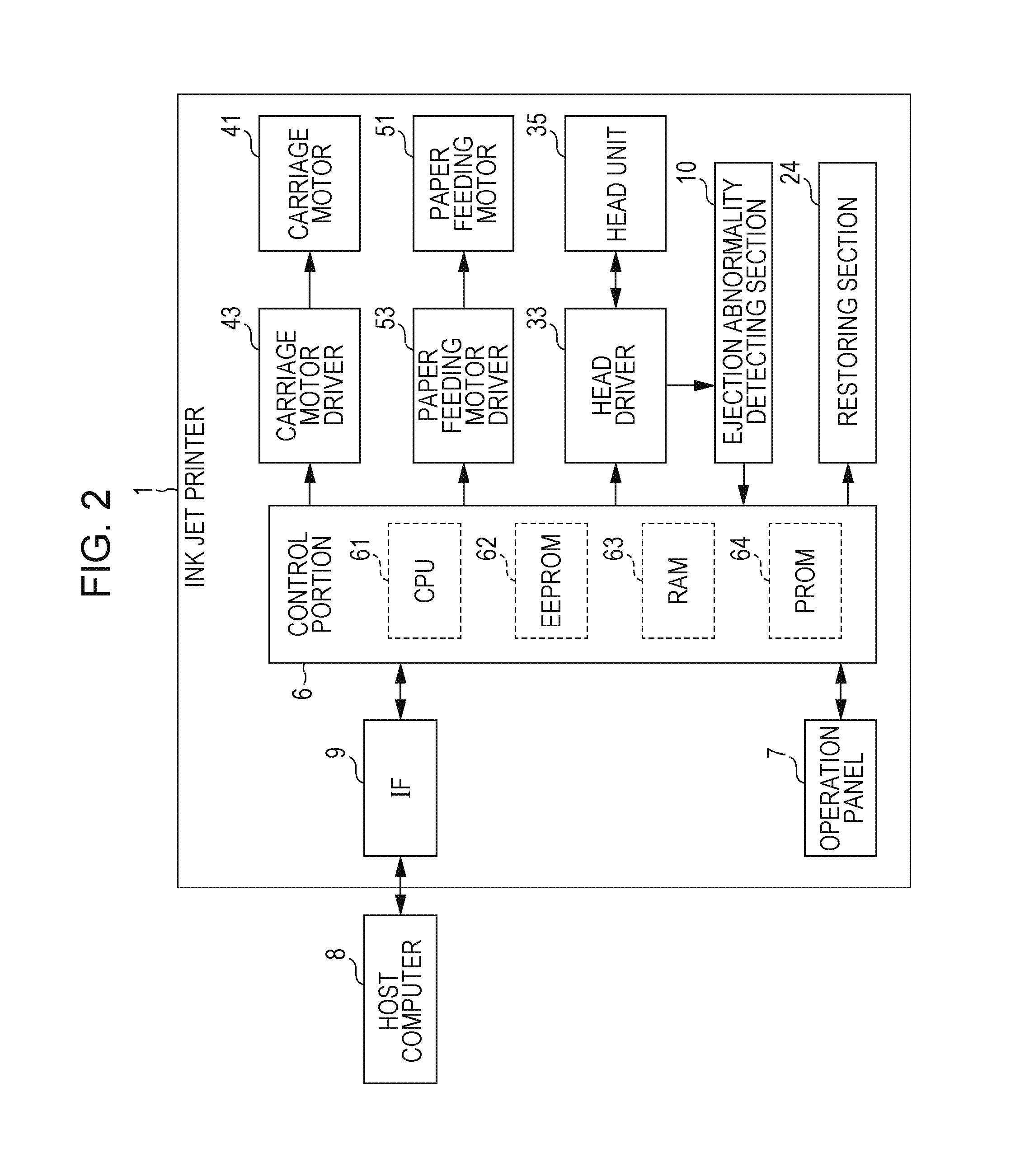
[0098]The operation panel 7 is configured with, for example, a liquid crystal display, an organic EL display, and an LED lamp, and includes a display portion (not illustrated) that displays an error message...

second embodiment

[0310]Next, another configuration example of the ink jet head is described. FIGS. 44 to 47 are cross-sectional views schematically illustrating other configurations of the ink jet head (head unit) respectively. Hereinafter, the configuration examples are described with reference to the drawings, but differences from the first embodiment are mainly described, so the same matters are omitted in the description.

[0311]The ink jet head 100A illustrated in FIG. 44 vibrates a vibration plate 212 by driving a piezoelectric element 200, and ejects ink (liquid) in a cavity 208 from nozzles 203. A stainless steel metal plate 204 is bonded to a stainless steel nozzle plate 202 in which the nozzles (holes) 203 are formed, through an adhesive film 205, and further the stainless steel metal plate 204 is bonded thereon through the adhesive film 205. Also, thereon, a communication opening forming plate 206 and a cavity plate 207 are sequentially bonded.

[0312]The nozzle plate 202, the metal plate 204...

third embodiment

[0326]Next, still another configuration example of the ink jet head is described. FIG. 48 is a perspective view illustrating the head unit 35 according to the third embodiment, and FIG. 49 is a cross-sectional view illustrating the head unit 35 (an ink jet head 100H) illustrated in FIG. 48. Hereinafter the configuration is described with reference to FIGS. 48 and 49. However, differences from the above embodiments are mainly described, so the same matters are omitted in the description.

[0327]The head unit 35 (the ink jet head 100H) illustrated in FIGS. 48 and 49 is a so-called film boiling ink jet-type (thermal jet-type) head unit, and has a configuration in which a supporting substrate 410, a substrate 420, an exterior wall 430, a partition 431, and a top plate 440 are bonded from the lower side of FIGS. 48 and 49 in this sequence.

[0328]The substrate 420 and the top plate 440 are installed to have a predetermined interval with interposing the exterior wall 430 and the plurality (6 ...


PUM


Abstract

A liquid ejecting apparatus includes: a liquid ejecting unit that ejects a liquid supplied through a liquid supply path from a nozzle; a maintenance unit that performs a maintenance operation of the liquid ejecting unit; and an ejection state detecting unit that is able to detect a state inside a pressure chamber communicating with the nozzle. The ejection state detecting unit detects a state inside the pressure chamber before the maintenance operation and at least one state inside the pressure chamber during the maintenance operation or after the maintenance operation, and is able to determine malfunction of at least one of the maintenance unit and function units arranged in the liquid supply path based on a change in a state inside the pressure chamber due to the maintenance operation.

Description

BACKGROUND[0001]1. Technical Field[0002]The present invention relates to a liquid ejecting apparatus such as a printer.[0003]2. Related Art[0004]As an example of the liquid ejecting apparatus, there is an ink jet-type printer that performs printing by supplying ink (liquid) contained in a liquid supply source to a liquid ejecting unit through a liquid supply path and ejecting the ink to a medium from a nozzle of the liquid ejecting unit. In addition, some of such printers have a replaceable expendable item such as a filter which collects a foreign substance such as a precipitate or a bubble in the ink. Further, the expendable item means an item which is changed into a different state when used and malfunctions. Hence, a degree of expendability of a filter indicates a degree of clogging. Also, in such a printer, in order to determine time for replacement of a filter as an expendable item, the degree of clogging of the filter is detected (for example, JP-A-2010-228147).[0005]However, ...

Claims


Application Information

Patent Timeline
Patent Type & Authority Applications(United States)
IPC IPC(8): B41J2/045
CPCB41J2/0451B41J2/04551B41J2/04555B41J2/04576B41J2/04578B41J2/0458B41J2/04581B41J2/04588B41J2/14153B41J2/14209B41J2/14233B41J2/14274B41J2/14314B41J2/16508B41J2/16517B41J2/16526B41J2/16579B41J2002/14354B41J2002/16573
Inventor MATSUMOTO, KEIJINAKAGAWA, SHIGENORISATO, MASAHIKOYAMAZAKI, TOSHINOBUSUZUKI, TOSHIYUKIYOSHIDA, TAKESHI
Owner SEIKO EPSON CORP
Why Eureka
Try Eureka