Wire harness

Active Publication Date: 2016-06-16
YAZAKI CORP
View PDF4 Cites 2 Cited by
  • Summary
  • Abstract
  • Description
  • Claims
  • Application Information

AI Technical Summary

Benefits of technology

[0014]According to the invention, there is obtained an effect that a shielding effect can be maintained even when the wire harness is bent. In addition,

Problems solved by technology

Therefore, there is a problem that the braid may be a relatively heavy member.
The

Method used


Image

  • Wire harness
  • Wire harness
  • Wire harness

Examples


Embodiment Construction

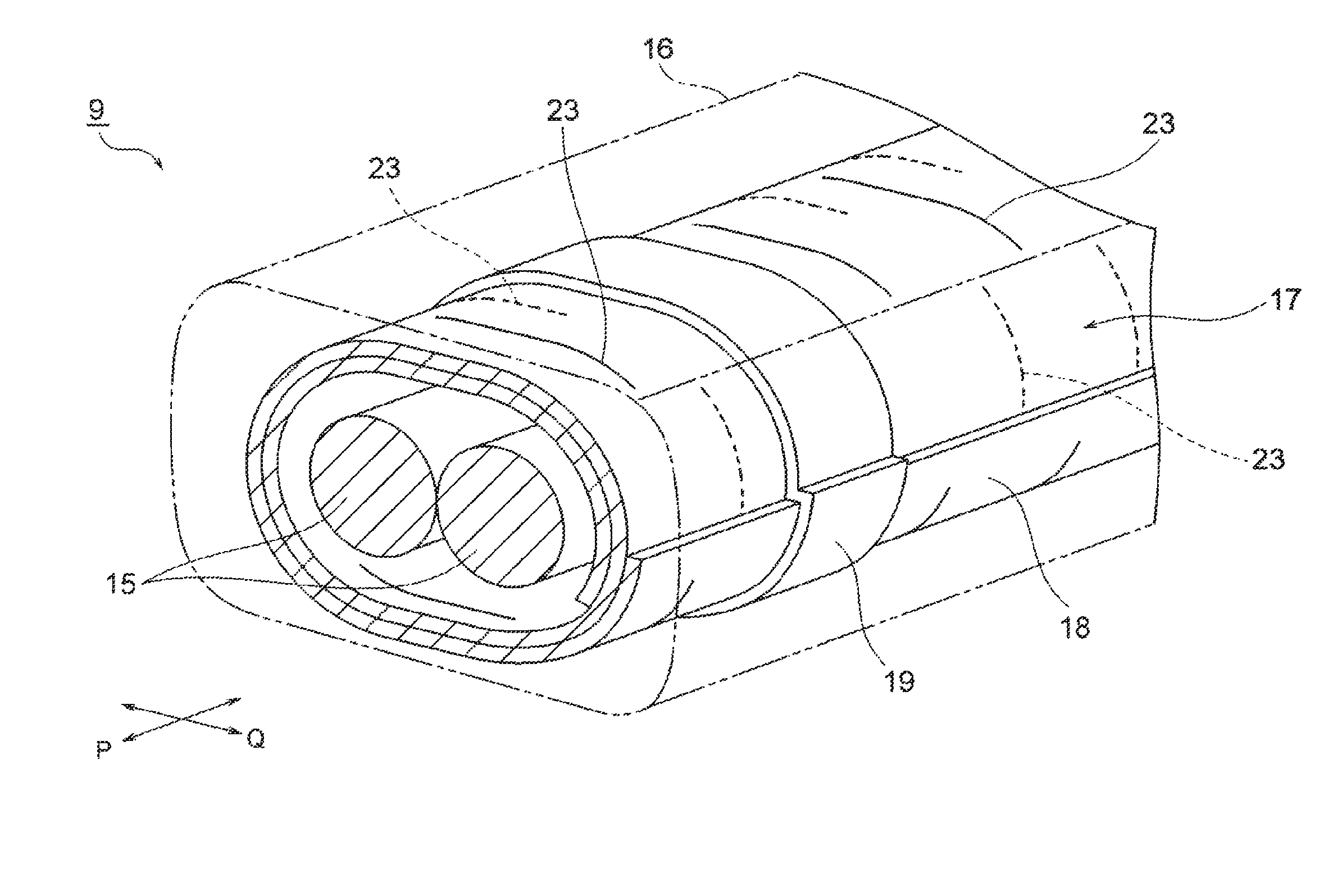
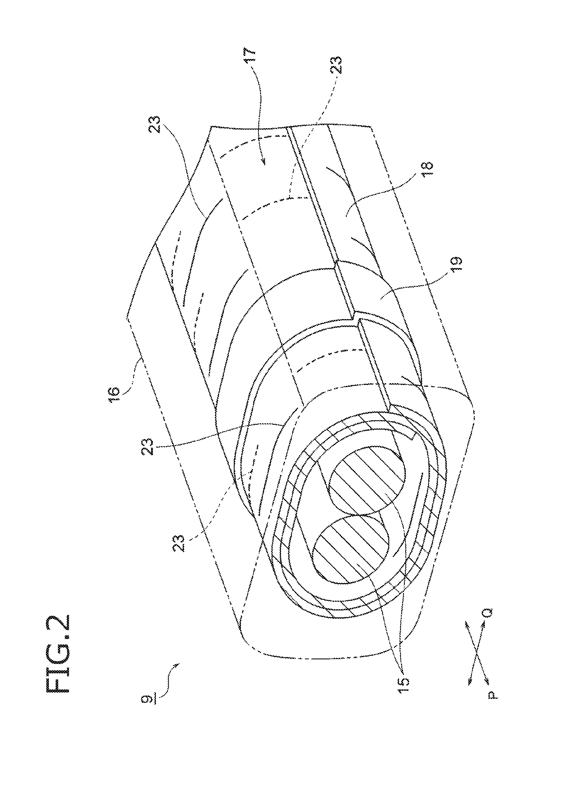
[0018]A wire harness includes one conducting path or a plurality of conducting paths, and a shield member which covers and shields the conducting path or paths. The wire harness is long enough to pass along a vehicle underfloor. The shield member includes a metal foil alone which has a plurality of slits each formed into a cut shape, or includes the metal foil and a base. In addition, the shield member has the plurality of slits, and is formed to be wrapped at least twice as a whole so that the plurality of slits do not overlap with each other.

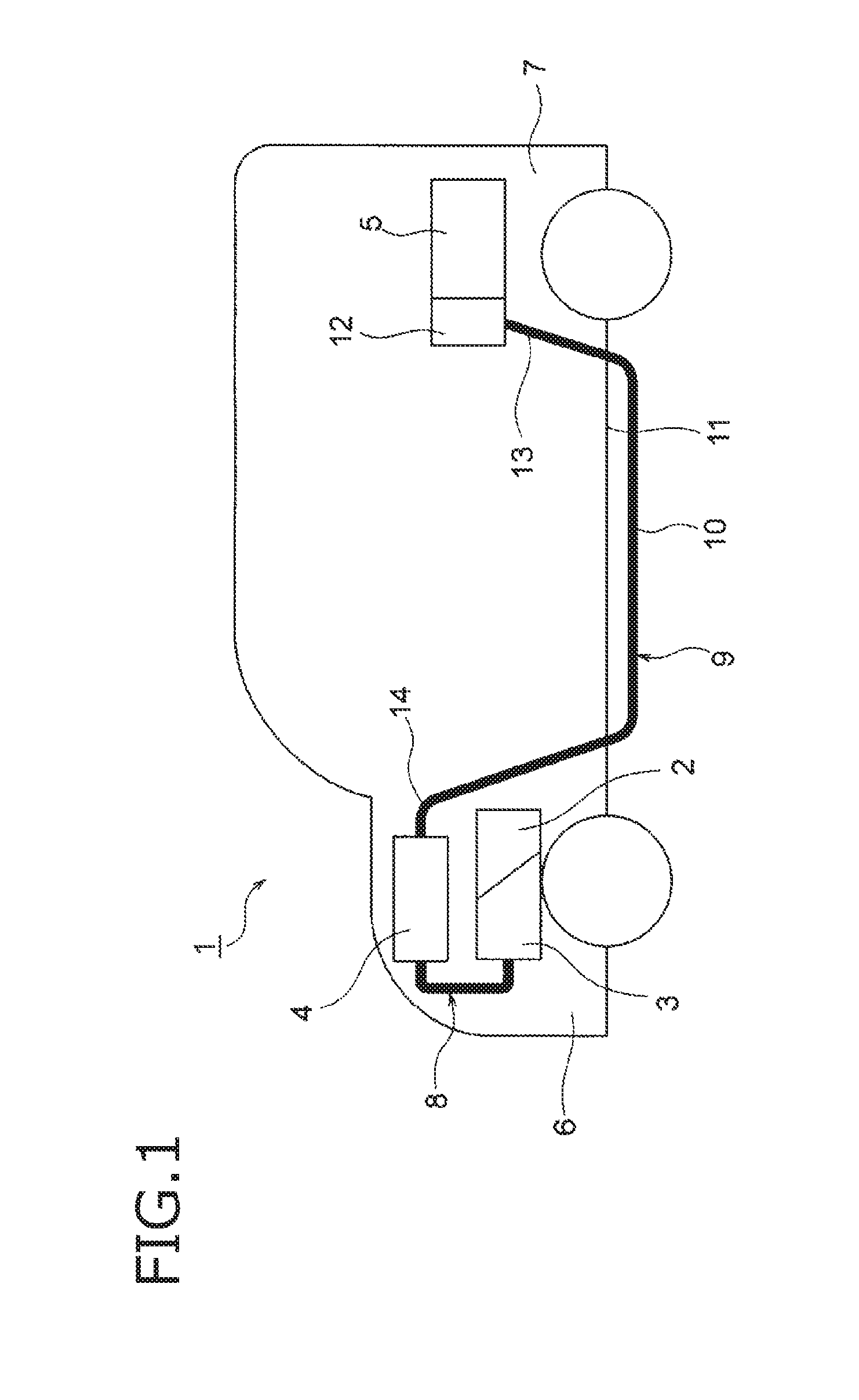
[0019]A wire harness according to an embodiment will be described below with reference to the drawings. FIG. 1 is a schematic view showing an arrangement state of the wire harness according to the embodiment of the invention. FIG. 2 is a perspective view showing configuration of the wire harness. FIG. 3 is a perspective view of a metal foil shield member.

[0020]In the embodiment, the invention is used for the wire harness arranged in a hybrid c...


PUM


Abstract

A wire harness (9) includes two high-voltage conducting paths (15), an exterior member (16) which receives and protects the high-voltage conducting paths (15), and a metal foil shield member (17) which covers and shields the high-voltage conducting paths (15) collectively. The metal foil shield member (17) includes a flexible sheet-like shield member body (18), and a retention member (19) which is used after the shield member body (18) is wrapped around the high-voltage conducting paths (15). A plurality of slits 23 are formed in the shield member body (18). The numerous slits (23) are disposed in places so as not to overlap with each other vertically when the shield member body (18) is wrapped around the two high-voltage conducting paths (15) twice.

Description

TECHNICAL FIELD[0001]The present invention relates to a wire harness which includes a conducting path, a shield member and an exterior memberBACKGROUND ART[0002]In the background art, for example, an inverter unit and a battery which are mounted in a hybrid car or an electric car are electrically connected to each other through a wire harness. The wire harness includes a thick high-voltage conducting path, a braided shield member which covers the high-voltage conducting path, and an exterior member which is disposed on an outer side of the braided shield member. In such a wire harness, the braided shield member is provided in order to prevent a peripheral device from malfunctioning due to noise radiated from the high-voltage conducting path. The braided shield member is a shield member including a well-known braid.[0003]The braid in the braided shield member is constituted by strands whose number is, for example, as high as 300. Therefore, there is a problem that the braid may be a ...

Claims


Application Information

Patent Timeline
IPC IPC(8): B60R16/02H01B7/00
CPCH01B7/0045B60R16/0215H02G3/0487
Inventor YOSHIDA, HIROYUKIADACHI, HIDEOMIOGA, TATSUYA
Owner YAZAKI CORP
Why Eureka
Try Eureka