

Bead gasket
- Summary
- Abstract
- Description
- Claims
- Application Information
AI Technical Summary
Benefits of technology
Problems solved by technology
Method used
Image

Examples
Embodiment Construction
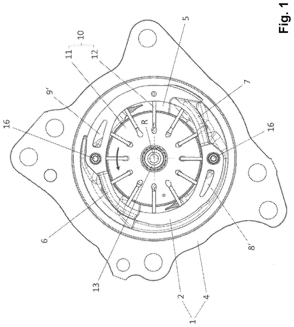
[0095]FIG. 1 shows a pump in an axial view onto a pump housing 1. A delivery chamber 5 is formed in the pump housing 1. The pump housing 1 comprises a housing circumferential wall 2, which surrounds the delivery chamber 5, and housing end-facing walls which axially delineate the delivery chamber 5 on both end-facing sides, of which one housing end-facing wall 4 can be seen. The other of the end-facing walls has been removed in FIG. 1 in order to reveal the interior of the delivery chamber 5.
[0096]The pump is embodied as a rotary pump and comprises a rotor 11, which can be rotated about an axis of rotation R in the delivery chamber 5, and multiple vanes 12 which are guided in slots of the rotor 11 such that they can be moved radially or at least substantially in the radial direction, as is typical in vane cell pumps. The rotor 11 and the vanes 12 together form a delivery member 10—in the example embodiment, an impeller—of the pump. An inner circumference of the housing circumferentia...
PUM
 Abstract
Description
Claims
Application Information