
Optimized sagd well placement utilizing temperature and electromagnetic measurements

a technology of electromagnetic measurement and temperature measurement, applied in the direction of borehole/well accessories, instruments, surveys, etc., can solve the problems of insufficient hydrocarbon mobility, reduced efficiency of particular advanced recovery process, and inability to increase the mobility of hydrocarbons high enough for production,

Active Publication Date: 2016-06-16
HALLIBURTON ENERGY SERVICES INC
View PDF1 Cites 12 Cited by
  • Summary
  • Abstract
  • Description
  • Claims
  • Application Information

AI Technical Summary

Benefits of technology

The patent text relates to methods and systems for tracking the placement of multiple wellbores relative to each other in wellbore drilling operations. The technical effect of the patent is to provide a more accurate and efficient way to position wellbores in relation to each other, which can improve the efficiency and effectiveness of advanced recovery procedures such as steam assisted gravity drainage (SAGD). The methods and systems involve using magnetic and thermal measurements to determine the relative distance and angle between the wellbores, and can also account for variations in geology and formation characteristics to optimize wellbore placement. The patent describes various techniques and tools that can be used to achieve this goal, including EM ranging, logging-while-drilling collar, and wellbore placement optimization methods.

Problems solved by technology

If the injector wellbore is positioned too far from the producer wellbore, the efficiency of the particular advanced recovery process may be reduced.
Likewise, if the wellbores are farther than optimal, mobility of hydrocarbons will not be increased high enough for production.
However, due to variations in the geology and formation characteristics, a constant distance is usually not always optimal for production.
Furthermore, the distance may not be selected properly, or may be selected too conservatively which can lead to non-optimal production.

Method used


Image

  • Optimized sagd well placement utilizing temperature and electromagnetic measurements
  • Optimized sagd well placement utilizing temperature and electromagnetic measurements
  • Optimized sagd well placement utilizing temperature and electromagnetic measurements

Examples


Embodiment Construction

[0013]The foregoing disclosure may repeat reference numerals and / or letters in the various examples. This repetition is for the purpose of simplicity and clarity and does not in itself dictate a relationship between the various embodiments and / or configurations discussed. Further, spatially relative terms, such as “beneath,”“below,”“lower,”“above,”“upper,”“uphole,”“downhole,”“upstream,”“downstream,” and the like, may be used herein for ease of description to describe one element or feature's relationship to another element(s) or feature(s) as illustrated in the figures. The spatially relative terms are intended to encompass different orientations of the apparatus in use or operation in addition to the orientation depicted in the figures. For example, if the apparatus in the figures is turned over, elements described as being “below” or “beneath” other elements or features would then be oriented “above” the other elements or features. Thus, the exemplary term “below” can encompass bo...


PUM


Abstract

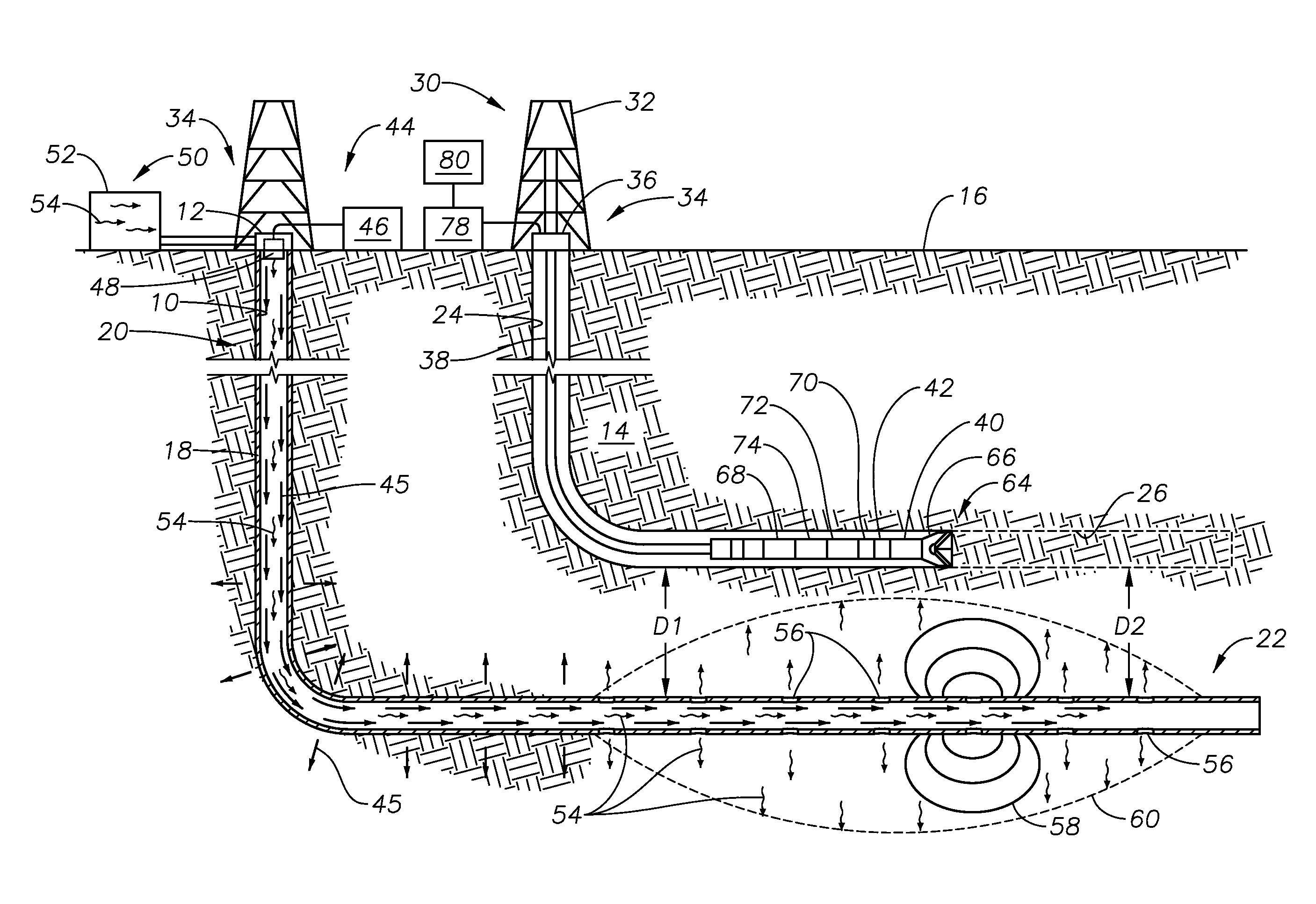
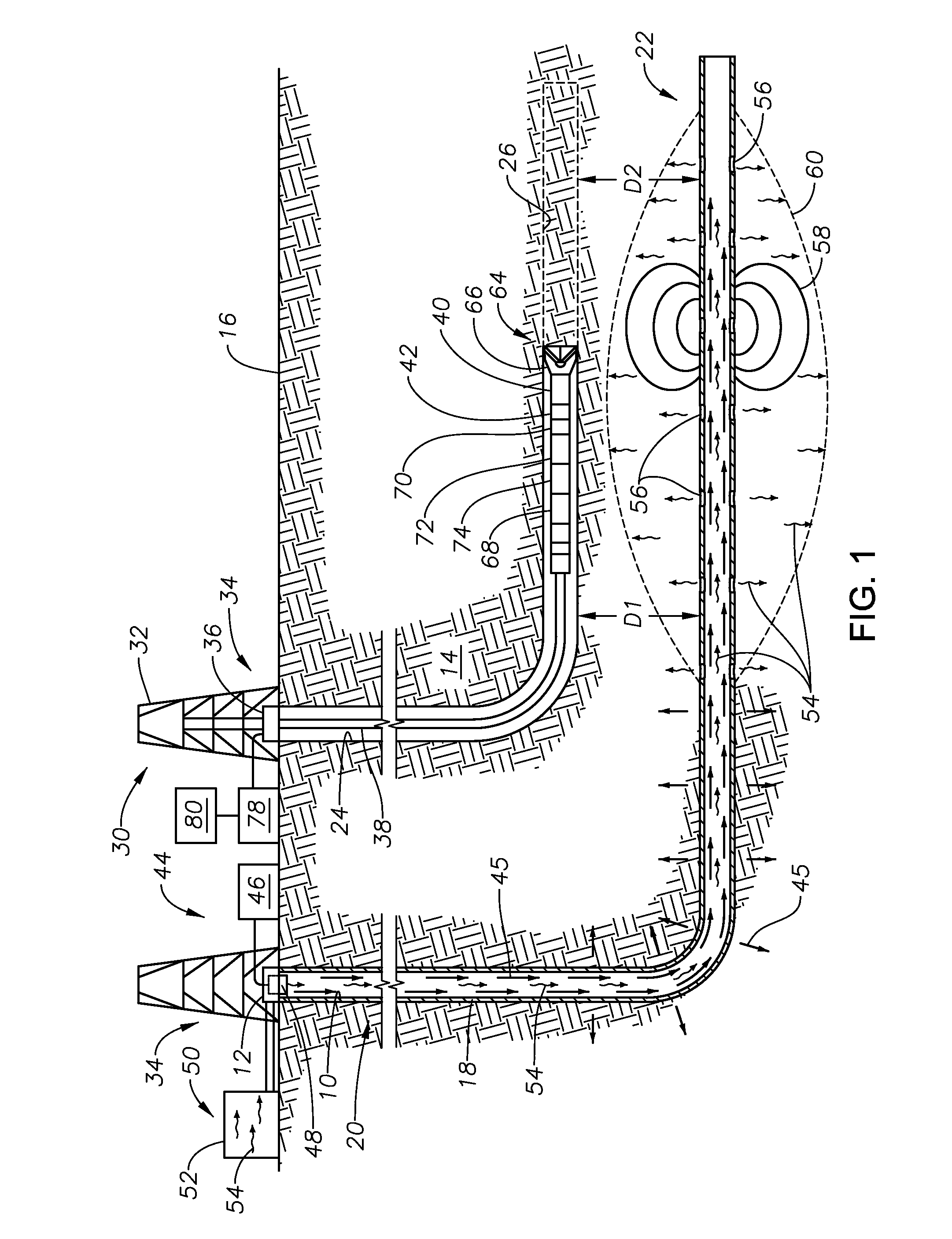
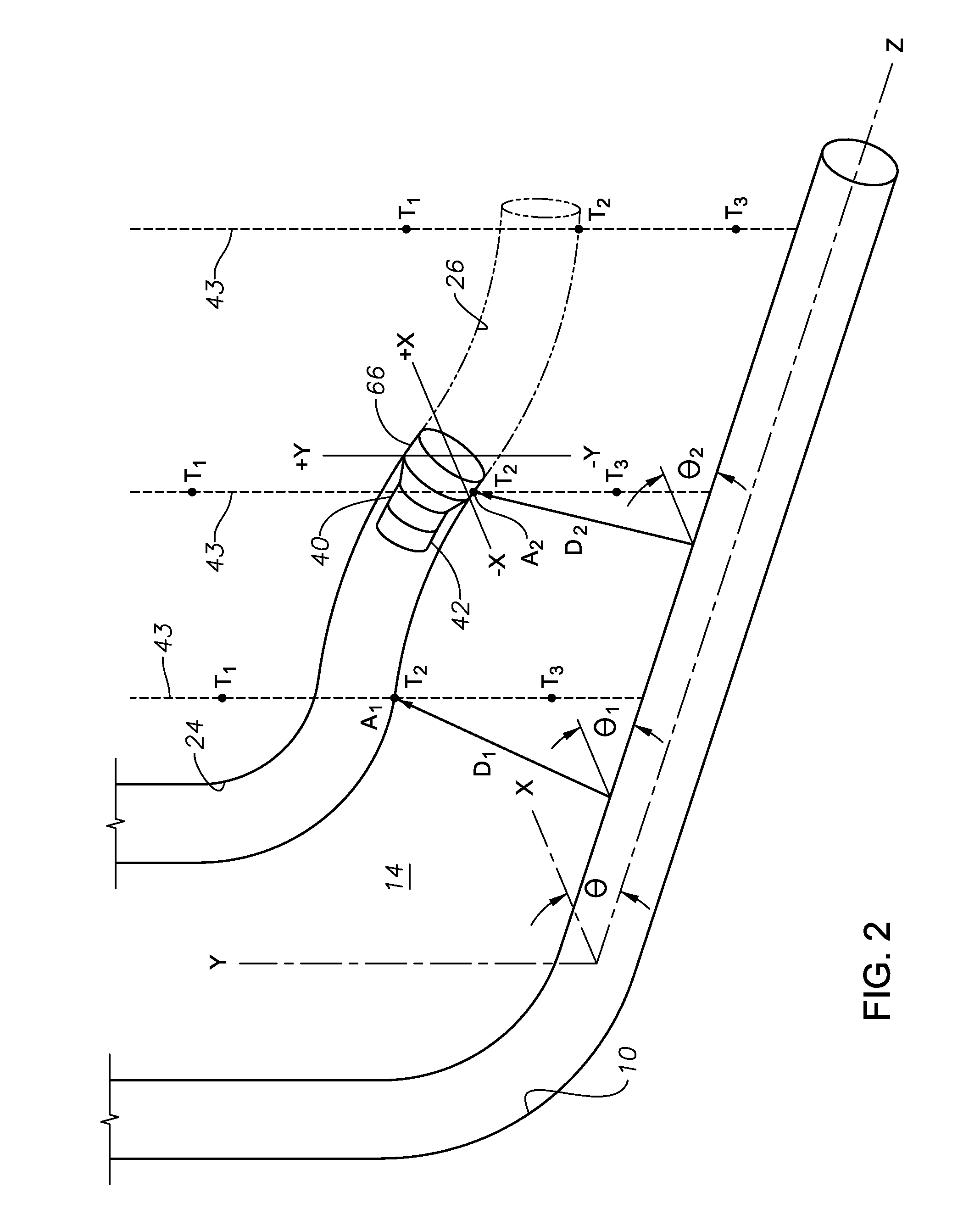
A system for optimizing placement of a second wellbore relative to a first wellbore utilizing i) steam injected into the first wellbore in combination with a temperature sensor located in the second wellbore and ii) electromagnetic (EM) fields emanating from the first wellbore in combination with an EM sensor in the second wellbore. The magnetic measurements made with the EM sensor are utilized to determine azimuthal placement of a wellbore, while temperature measurements made with the temperature sensor are utilized to determine distance for placement of the wellbore.

Description

FIELD OF THE DISCLOSURE[0001]The disclosure relates to wellbore drilling operations, and more particularly to methods and systems for tracking the drilling of multiple wellbores relative to one another. Most particularly, the disclosure relates to methods and systems for determining the relative location of a reference wellbore from a wellbore being drilled using magnetic and thermal measurements.BACKGROUND OF THE DISCLOSURE[0002]As easy-to-access and easy-to-produce hydrocarbon resources are depleted, there is an increased demand for more advanced recovery procedures. One such procedure is steam assisted gravity drainage (SAGD), a procedure that utilizes steam in conjunction with two spaced apart wellbores. Specifically, SAGD addresses the mobility problem of heavy oil in a formation through the injection of high pressure, high temperature steam into the formation. This high pressure, high temperature steam reduces the viscosity of the heavy oil in order to enhance extraction. The ...

Claims


Application Information

Patent Timeline
IPC IPC(8): E21B47/022G01V3/20E21B43/24G01V9/00E21B7/06E21B47/024
CPCE21B47/02216E21B7/06E21B47/024E21B43/2406G01V9/005G01V3/20E21B43/2408E21B47/022E21B7/04E21B47/07E21B47/0228
Inventor DONDERICI, BURKAYUPSHALL, MALCOLM
Owner HALLIBURTON ENERGY SERVICES INC
Learn More