
Read-out electronics for DC squid magnetic measurements

a technology of dc squid and magnetic measurement, applied in the direction of magnetic measurement, magnetic field measurement using superconductive devices, instruments, etc., can solve the problems of fll losing lock, invalidating any measurement in progress, and not being practicable in a field setting for dc squid sensor systems for non-destructive testing/evaluation of materials or structures

Inactive Publication Date: 2002-07-16
HONEYWELL INT INC
View PDF11 Cites 29 Cited by
  • Summary
  • Abstract
  • Description
  • Claims
  • Application Information

AI Technical Summary

Problems solved by technology

DC SQUID sensor systems for non-destructive testing / evaluation of materials or structures or for biomagnetic measurements are not yet practical for use in a field setting (i.e., environments containing high levels of magnetic interference).
In magnetically unshielded environments, large amplitude or high slew rate external stray magnetic fields from 50 / 60 Hz AC power lines, AM broadcast transmitters, small changes in the Earth's magnetic field, and other sources, cause the FLL to lose lock, thereby invalidating any measurement in progress.
Furthermore, the prior art employs traditional twisted-pair wires which are highly undesirable for several reasons: they have a high degree of linear attenuation versus frequency that severely distorts square waves of even moderate frequencies, they allow for a large amount of radiated leakage and corresponding susceptibility to radio-frequency interference, and they have a highly variable characteristic impedance that changes with mechanical stress and is difficult to impedance match.
The incorporation of digital signal processing (DSP) technology into the FLL of a DC SQUID has been attempted, but results have been limited due to inherent delays associated with signal acquisition, processing and reconstruction of the feedback signal, and the maximum clock frequency of the DSP.
Because of these problems, previous attempts to incorporate DSP into an FLL have failed to increase the operating frequency above that obtainable with standard analog read-out systems.
For these reasons, DC SQUIDs are restricted to controlled environments which are shielded from magnetic interference and are typically expensive, bulky, and non-portable.

Method used


Image

  • Read-out electronics for DC squid magnetic measurements
  • Read-out electronics for DC squid magnetic measurements
  • Read-out electronics for DC squid magnetic measurements

Examples


Embodiment Construction

, below.

A preferred embodiment of the present invention is described in detail below with reference to the attached drawing figures, wherein:

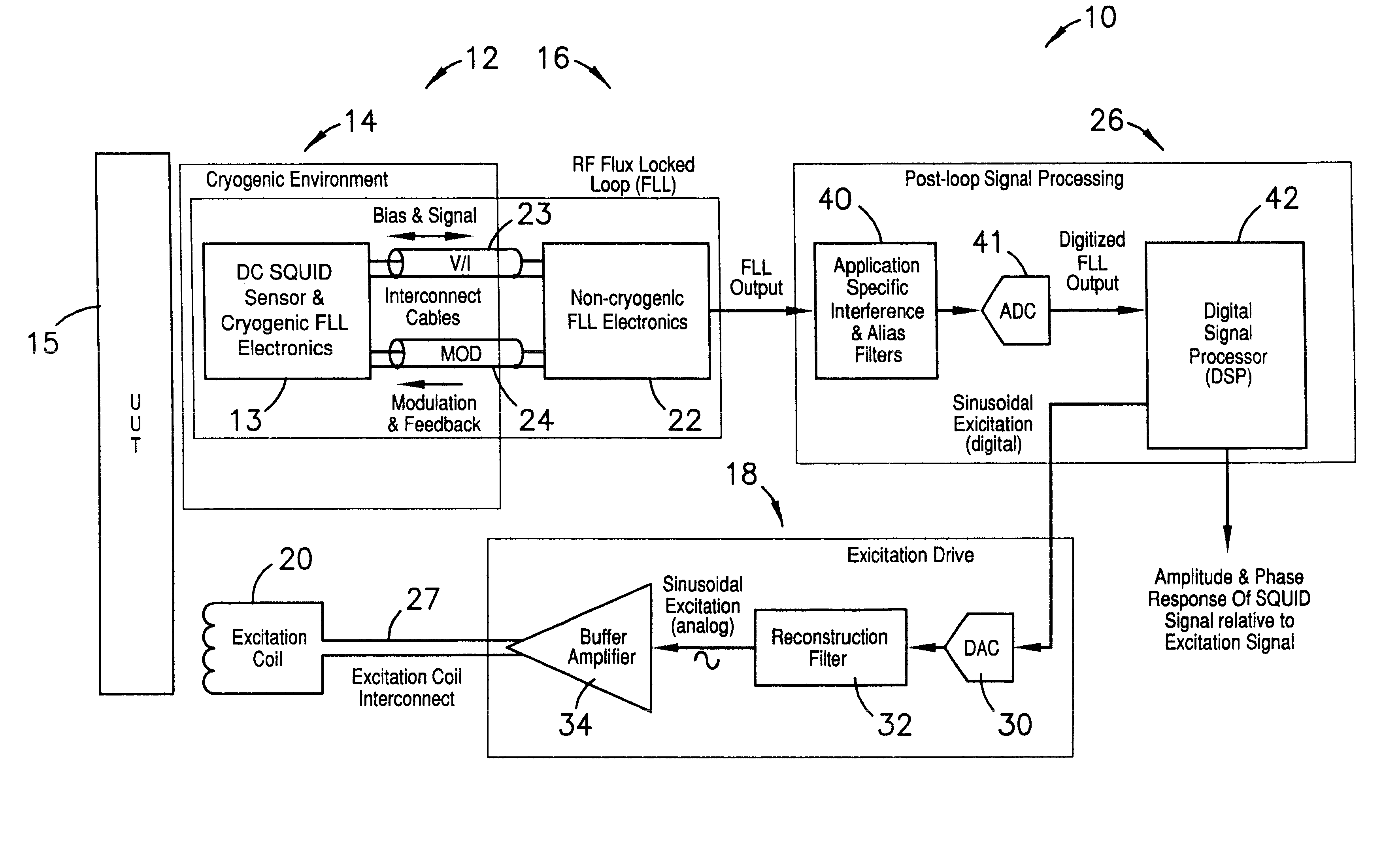
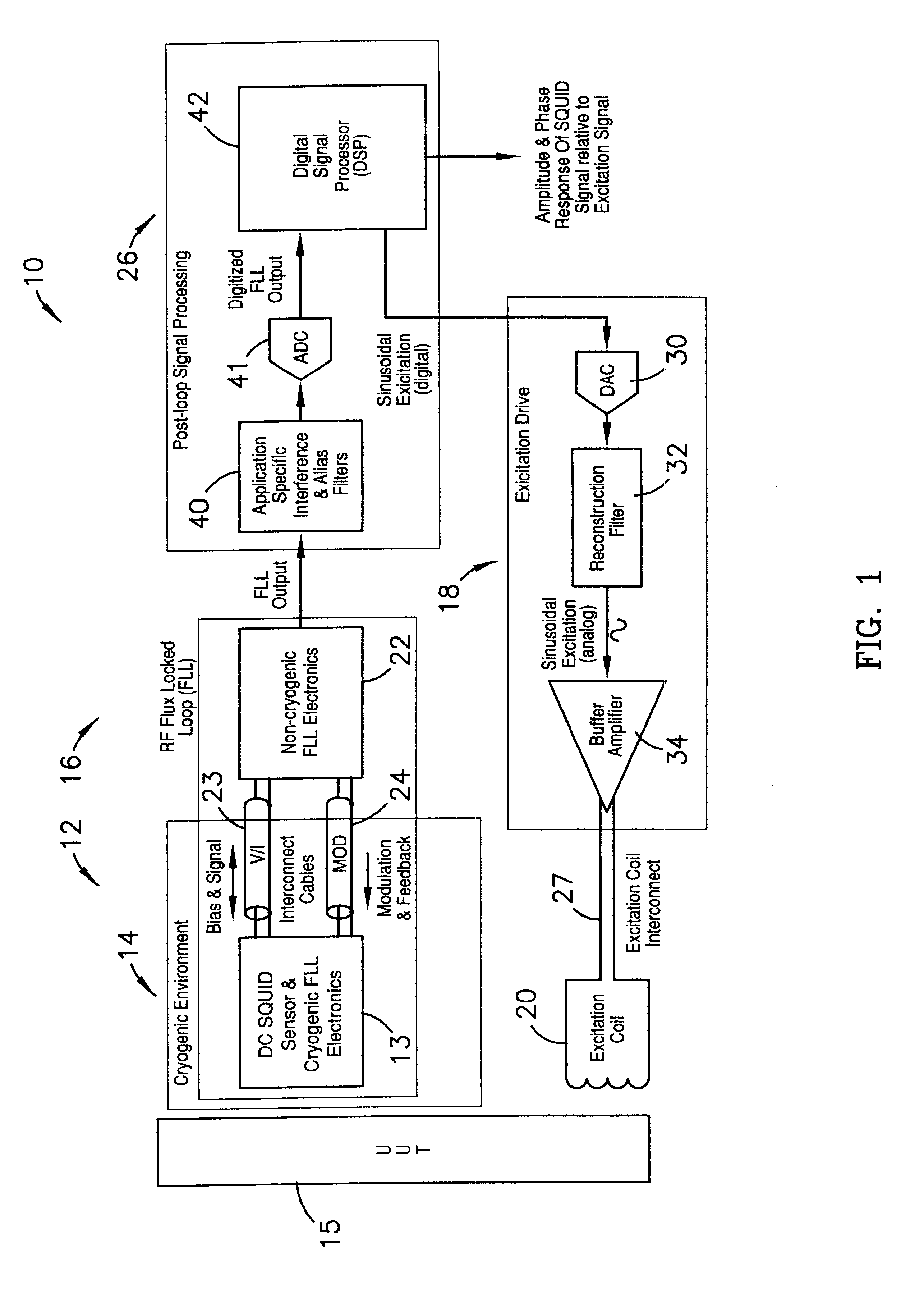
FIG. 1 is a block diagram illustrating a first preferred embodiment of the major components of the read-out electronics of the present invention.

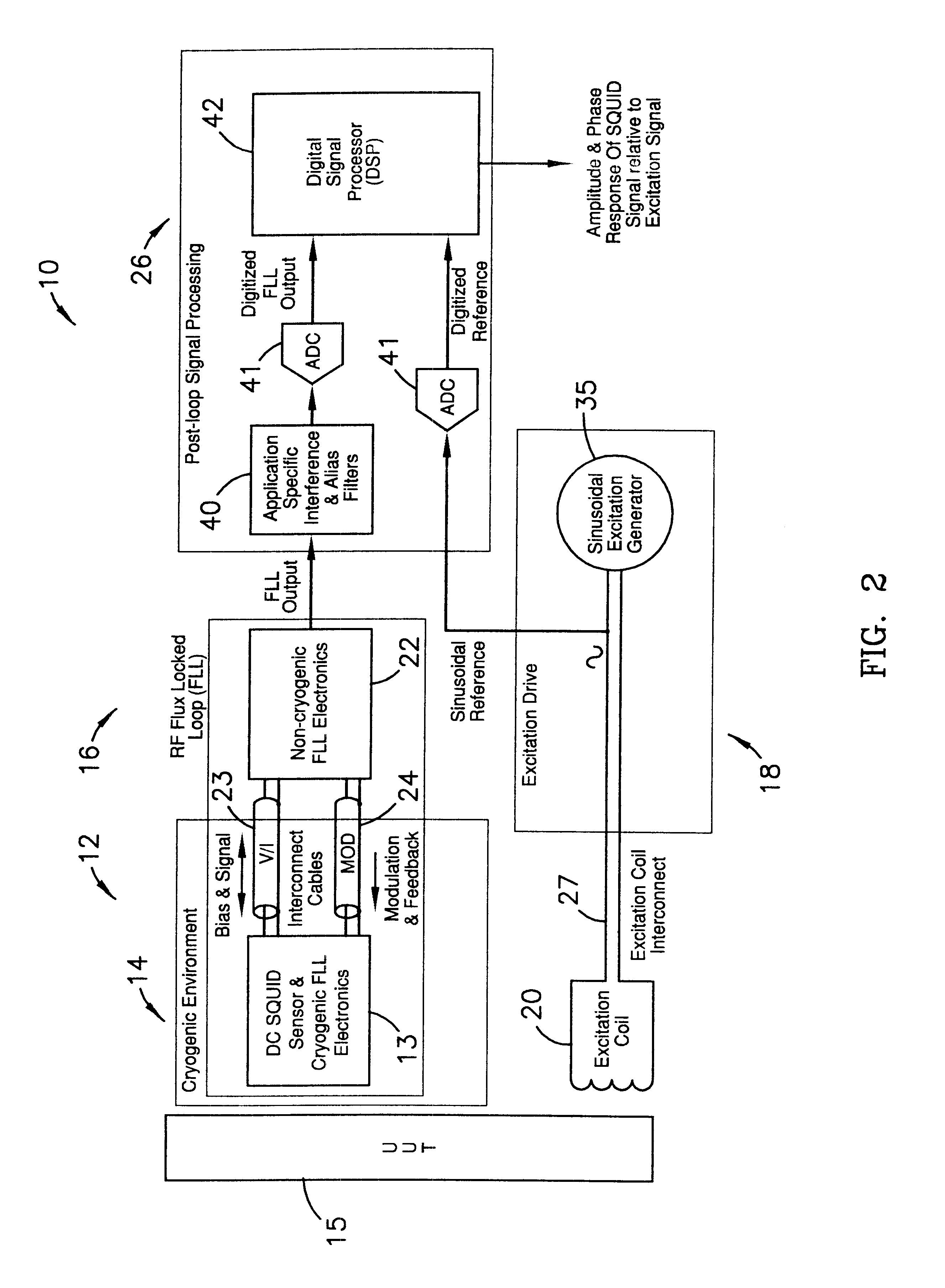
FIG. 2 is a block diagram illustrating a second preferred embodiment of the major components of the read-out electronics of the present invention.

FIG. 3 is a block diagram illustrating a preferred embodiment of the flux locked loop component of the present invention.

FIG. 4 is a circuit diagram illustrating a preferred embodiment of the sharpener circuit of the present invention.

FIG. 5 is block diagram illustrating a first preferred embodiment of the digital signal processing component of the present invention.

FIG. 6 is a block diagram illustrating a second preferred embodiment of the digital signal processing component of the present invention.

Referring to FIGS. 1 and 2, a DC SQUID magnetic measurement...


PUM


Abstract

Read-out electronics for DC SQUID sensor systems, the read-out electronics incorporating low Johnson noise radio-frequency flux-locked loop circuitry and digital signal processing algorithms in order to improve upon the prior art by a factor of at least ten, thereby alleviating problems caused by magnetic interference when operating DC SQUID sensor systems in magnetically unshielded environments.

Description

1. Field of the InventionThe present invention relates to electronic read-out devices, and, more particularly, to devices for providing improved electronic read-out of magnetic measurements made by direct current superconducting quantum interference devices (DC SQUIDs).2. Description of the Prior ArtDC SQUIDs are small, cryogenically-cooled magnetic sensors that comprise a ring of superconducting material interrupted by two Josephson junctions. DC SQUIDs are designed to detect changes in magnetic flux, and, when suitably biased with a small DC current, will exhibit a magnetic flux sensitivity noise floor of approximately 1.times.10.sup.-6 .PHI..sub.0 / Hz for low temperature devices that operate near 4 degrees Kelvin (typically cooled by liquid Helium), and approximately 7.times.10.sup.-6 .PHI..sub.0 / Hz for high temperature devices that operate near 77 degrees Kelvin (typically cooled by liquid Nitrogen). Furthermore, DC SQUIDs exhibit a transfer function that converts magnetic fl...

Claims


Application Information

Patent Timeline
IPC IPC(8): G01R33/035
CPCG01R33/0356Y10S505/846
Inventor GANTHER, JR., KENNETH R.SNAPP, LOWELL D.
Owner HONEYWELL INT INC
Learn More