
Fast flux locked loop

a fast flux and lock loop technology, applied in pulse technique, magnetic field measurement using superconductive devices, instruments, etc., can solve the problems of inability to use dc squid sensor systems for non-destructive testing/evaluation or biomagnetic measurement in a field setting, loss of lock lock, measurement in progress invalidation, etc., to improve system noise performance, reduce effective amplifier input noise, and improve control loop stability

Inactive Publication Date: 2002-09-10
HONEYWELL INT INC
View PDF8 Cites 25 Cited by
  • Summary
  • Abstract
  • Description
  • Claims
  • Application Information

AI Technical Summary

Benefits of technology

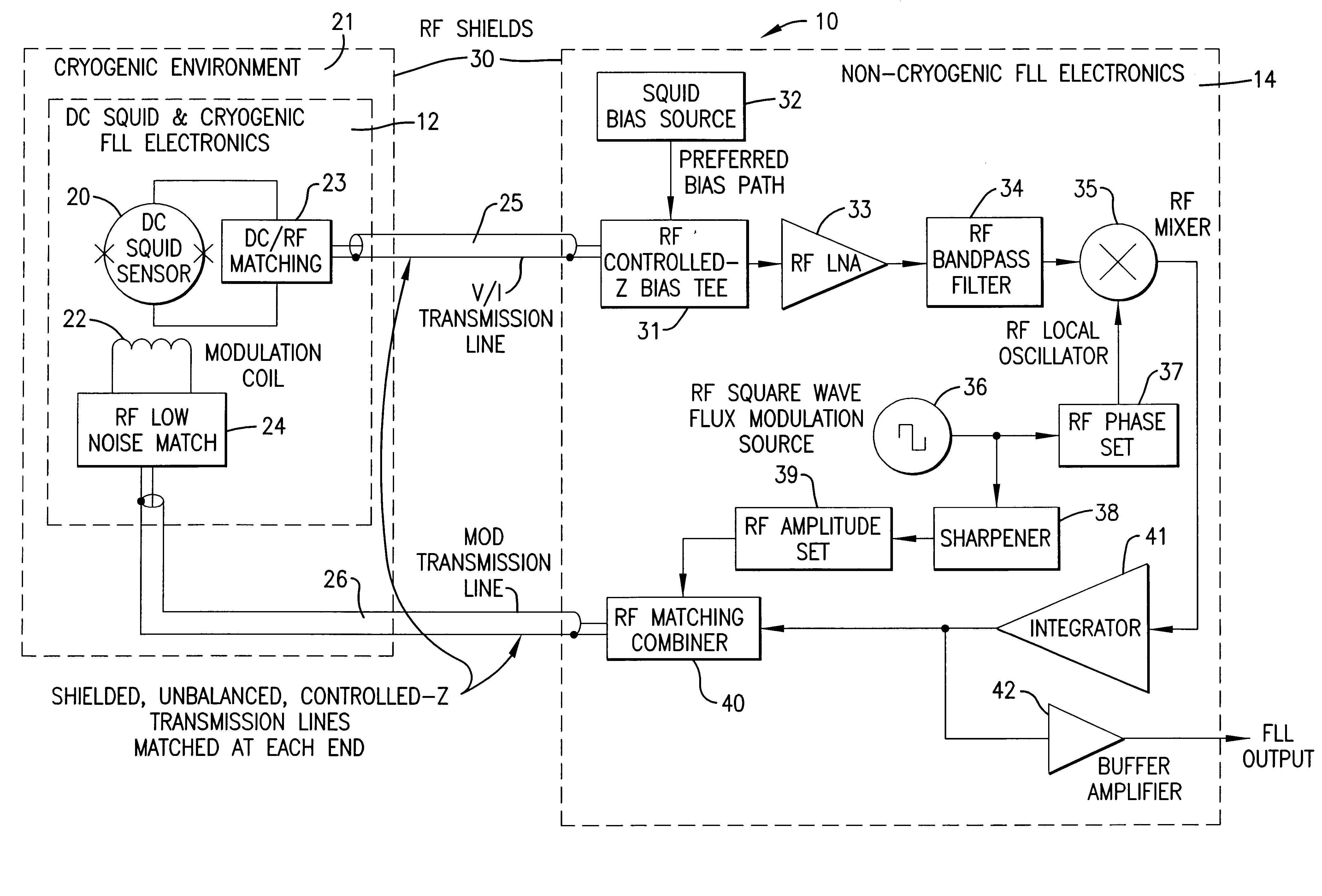
A single RF low noise amplifier is preferred, though multiple RF low noise amplifiers operating in parallel may also be used. The signal from the DC SQUID sensor 20 is coupled into at least one such RF low noise amplifier 33 via the DC / RF matching circuit 23 which matches the impedance of the Upper transmission line 25 to the impedance of the sensor 20. The RF low noise amplifier 33 has a bandwidth that is at least two times the loop tracking bandwidth of the flux locked loop 12,14 as a whole and is centered at the flux modulation frequency. The RF low noise amplifier 33 is constructed with readily available low noise components and, preferably, has a gain adjustment circuit for fine tuning control loop dynamics. The RF low noise amplifier 33 has a higher percentage of the total loop gain than that in the DC portion of the control loop, which benefits control loop DC stability. The RF low noise amplifier 33 feeds the RF bandpass filter 34.
The RF bandpass filter 34 is used to limit the noise bandwidth to twice the tracking bandwidth and to remove noise at odd harmonics of the flux modulation frequency that would otherwise mix down to baseband in the RF mixer 35 and degrade system noise performance. The RF bandpass filter 34 is preferably a single pole bandpass filter because the single pole response provides for minimum added delay through the loop.
The flux modulation source 36 can be virtually any square wave generator that produces sharp rise and fall times. In the preferred embodiment, the flux modulation source 36 is a low cost clock module operating at a duty cycle of approximately 50%. The flux modulation signal drives the phase setting circuit 37 which causes the RF mixer 35 to be coherent with the input signal from the low noise amplifier 33 at the proper phase angle for operation of the RF mixer 35.
The preferred embodiment of the integrator 41 performs both integration and differentiation functions. The integrator 41 is comprised of two passive integrator stages, each driving a wideband gain block. This arrangement aids in maximizing the frequency response of the overall integrator 41. The second integrator stage low noise gain block provides the output of the integrator 41. This output signal is attenuated and converted into a controlled source impedance for signal summation in the matching combiner circuit 40. The output of the integrator 41 is also the usable output signal of the non-cryogenic electronics 14. A buffer amplifier 42 is used to buffer the output signal. Because this signal is the identical image of the external flux, the signal characteristics of the external flux can be measured from the buffered output signal of the integrator 41.
From the preceding description, it can be seen that the flux locked loop of the present invention extends the frequency of operation of flux locked loops, thereby enabling them to better track undesired magnetic interference that is summed with the desired signals to be measured. This interference can be separated and removed from the desired signals by analog or digital signal processing of the FLL output signal, as shown in the copending patent application entitled "Read-Out Electronics for DC SQUID Magnetic Measurements", Ser. No. 09 / 596,190, filed Jun. 16, 2000. In applications involving DC SQUID read-out electronics, the flux locked loop of the present invention is essential to achieving practical operation in unshielded environments.

Problems solved by technology

DC SQUID sensor systems for non-destructive testing / evaluation or for biomagnetic measurements are not yet practical for use in a field setting (i.e., environments containing high levels of magnetic interference).
These limitations result in the FLL losing lock when exposed to large amplitude or high slew rate external stray magnetic fields from 50 / 60 Hz AC power lines, AM broadcast transmitters, small changes in the Earth's magnetic field, and other sources present in unshielded environments.
When the FLL loses lock, any measurement in progress is invalidated.

Method used


Image

  • Fast flux locked loop
  • Fast flux locked loop
  • Fast flux locked loop

Examples


Embodiment Construction

, below.

A preferred embodiment of the present invention is described in detail below with reference to the attached drawing figures, wherein:

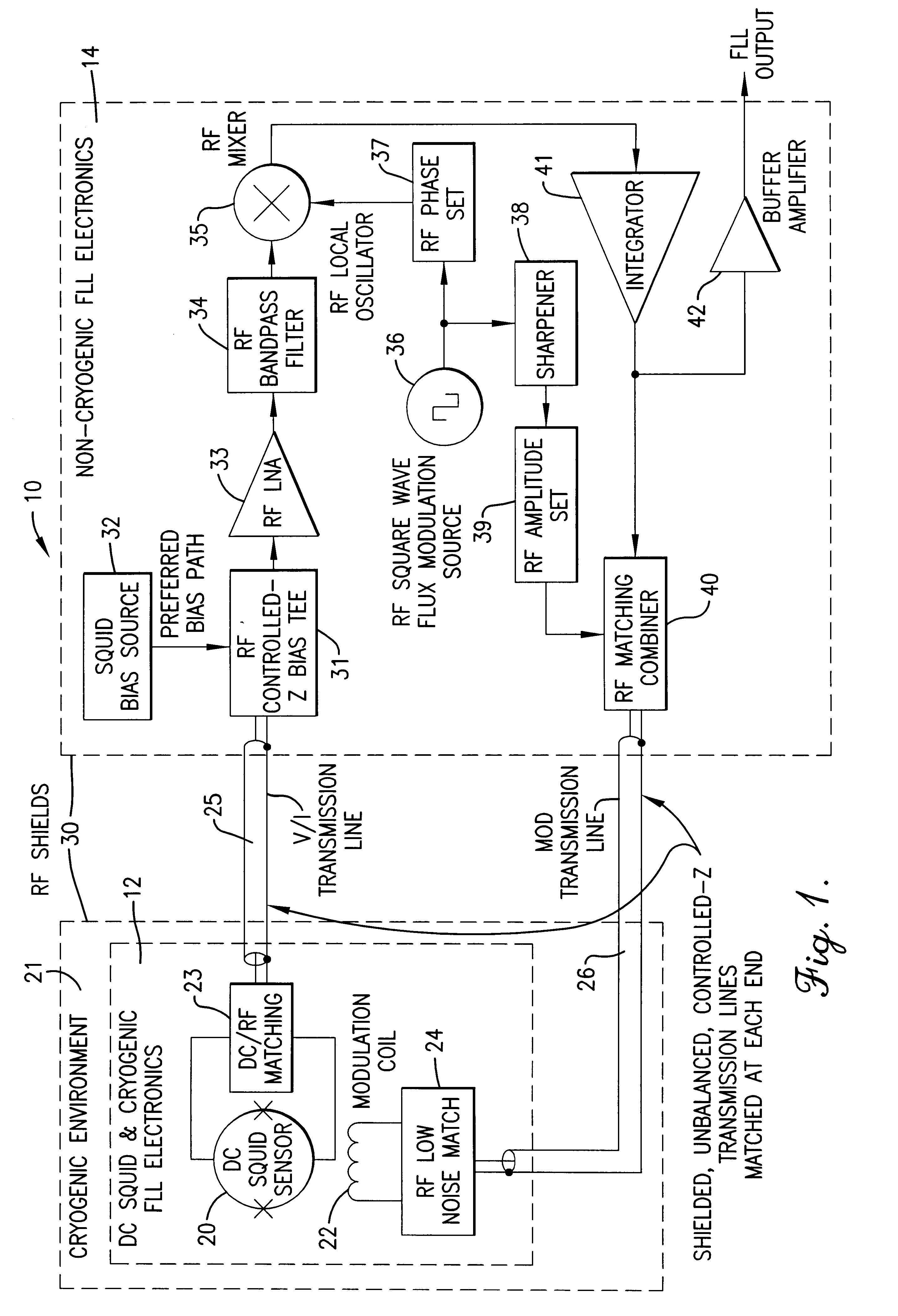
FIG. 1 is a block diagram illustrating a flux locked loop constructed in accordance with a preferred embodiment of the present invention.

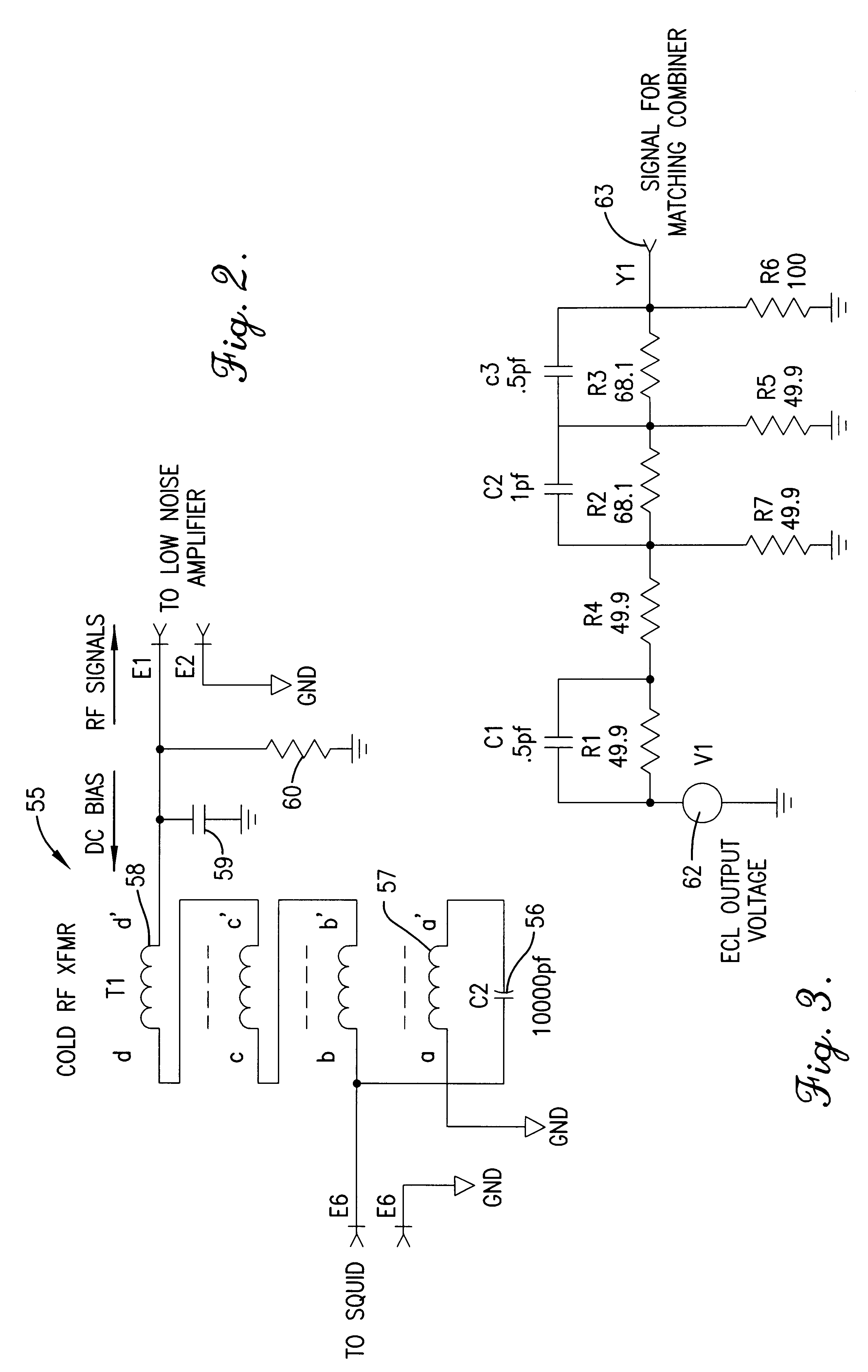
FIG. 2 is a circuit schematic illustrating a preferred embodiment of the cold RF transformer component of the present invention.

FIG. 3 is a circuit diagram illustrating a preferred embodiment of the sharpener circuit of the present invention.

Referring to FIG. 1, a DC SQUID flux locked loop feedback system 10 is shown comprising a DC SQUID with cryogenic flux locked loop electronics 12 and non-cryogenic flux locked loop electronics 14. Such a DC SQUID feedback system 10 is a major component of read-out electronics for. a DC SQUID magnetic measurement system, as described and shown in the copending patent application entitled "Read-Out Electronics for DC SQUID Magnetic Measurements", Ser. No. 09 / 596,190, filed J...


PUM


Abstract

A flux locked loop for providing an electrical feedback signal, the flux locked loop employing radio-frequency components and technology to extend the flux modulation frequency and tracking loop bandwidth. The flux locked loop of the present invention has particularly useful application in read-out electronics for DC SQUID magnetic measurement systems, in which case the electrical signal output by the flux locked loop represents an unknown magnetic flux applied to the DC SQUID.

Description

1. Field of the InventionThe present invention relates to electronic circuits and signals, and, more particularly, to flux locked loops for providing feedback signals, including feedback signals to direct current superconducting quantum interference devices (DC SQUIDs).2. Description of the Prior ArtFlux locked loops are typically used in the read-out electronics of magnetic measurement systems employing DC SQUIDs. DC SQUIDs are small, cryogenically-cooled magnetic sensors that comprise a ring of superconducting material interrupted by two Josephson junctions. DC SQUIDs are designed to detect changes in magnetic flux and can be used as flux-to-voltage converters. The standard read-out method for DC SQUID measurements is to inject a magnetic field modulation signal into the DC SQUID and then, using a flux locked loop (FLL) circuit, sense changes in the modulating signal due to external magnetic fields. The FLL provides negative feedback to the DC SQUID in order to maintain linear ope...

Claims


Application Information

Patent Timeline
Patent Type & Authority Patents(United States)
IPC IPC(8): G01R33/035
CPCG01R33/0356
Inventor GANTHER, JR., KENNETH R.SNAPP, LOWELL D.
Owner HONEYWELL INT INC
Learn More