
Magnetic measurement system and method for measuring magnetic field

a magnetic field and measurement system technology, applied in the field of magnetic measurement system for batteries, can solve the problems of inability to record the magnetic field generated by electric current in the battery, the inability to evaluate the difficulty of evaluating a local part of the battery, etc., and achieve the effect of accurate measuremen

Inactive Publication Date: 2013-03-07
HITACHI LTD
View PDF3 Cites 30 Cited by
  • Summary
  • Abstract
  • Description
  • Claims
  • Application Information

AI Technical Summary

Benefits of technology

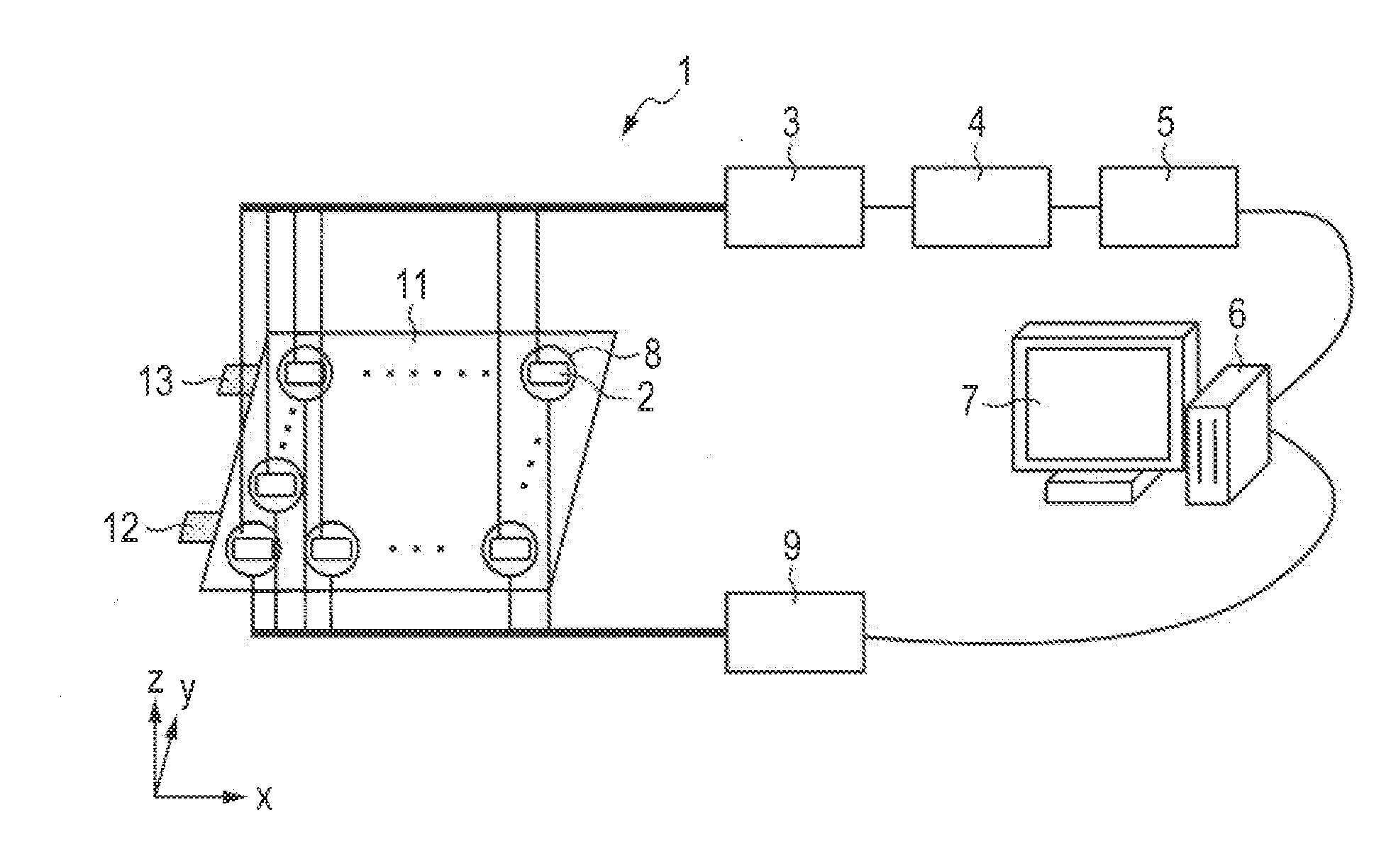
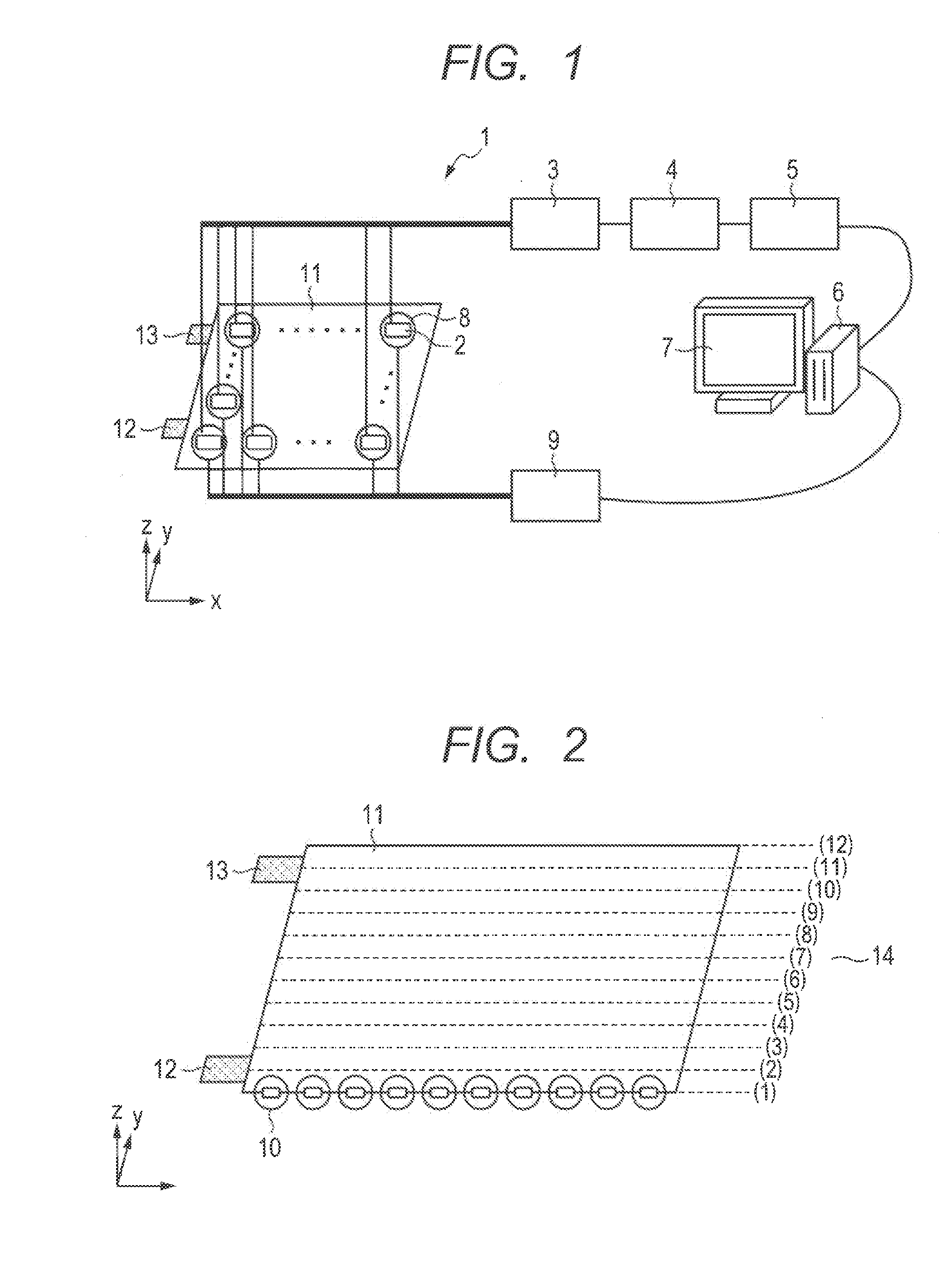
This patent is about a technique to accurately measure magnetic signals generated by electric current in a lithium-ion battery during charging and discharging, without getting the magnetic sensor output saturated. This can be done even in an environment with strong magnetic noise. Additionally, the technique helps to visualize the electric current distribution in the battery.

Problems solved by technology

Therefore, although evaluation for performance and quality of a whole battery has been possible, evaluation of a local part in the battery has been difficult.
Documents 1 to 3 are applied to the lithium-ion battery during charging and discharging, a problem with magnetic noise arises.
As a result, the magnetic field generated by electric current in the battery cannot be recorded.
However, at the time of magnetic measurement of the lithium-ion battery during charging and discharging, the magnetic sensor is saturated depending on the intensity of the magnetic field generated from the surrounding device and the lithium-ion battery, and thereby, the measurement by the magnetic sensor becomes difficult.

Method used


Image

  • Magnetic measurement system and method for measuring magnetic field
  • Magnetic measurement system and method for measuring magnetic field
  • Magnetic measurement system and method for measuring magnetic field

Examples


first embodiment

of Method

[0056]As the first embodiment of a method according to the invention, a procedure in which environment noise of a magnetic signal from a lithium-ion battery recorded when charging is removed by using a magnetic signal measured before a start of charging (a correction-magnetic field signal) and electric current distribution in the lithium-ion battery is accurately displayed is described below.

[0057]A flow chart of the processes of the analysis procedure in this embodiment is illustrated in FIG. 4A. In the following description, a step number corresponding to each process of procedure is represented in parentheses.

[0058]First, with ambient noise cancelled by each cancel coil 8, the procedure is started (201), and for each magnetic sensor 2, an average magnetic signal for correction is calculated from a magnetic signal recorded before charge (a correction-magnetic field signal) (202). Subsequently, for each magnetic sensor an average magnetic signal for charging is calculated ...

second embodiment

of Method

[0075]In the second embodiment, environment noise of a magnetic signal from a lithium-ion battery recorded when discharging is removed by using a magnetic signal recorded before a start of discharge (a correction-magnetic field signal) and electric current distribution in the battery is accurately displayed.

[0076]A flow chart of the processes of the analysis procedure in this embodiment is illustrated in FIG. 4B. When the procedure is started (201), firstly, with ambient magnetic noise cancelled by each cancel coil, an average magnetic signal for correction is calculated for each magnetic sensor 2 from a magnetic signal recorded before discharge (a correction-magnetic field signal) (202). Next, for each magnetic sensor, an average magnetic signal for discharging is calculated (203-2), and a difference is calculated by subtracting the average magnetic signal for data correction from the average magnetic signal for discharging (204-2). Electric current distribution is then ca...

third embodiment

of Method

[0085]In the third embodiment, a magnetic field variation is calculated using a magnetic signal at a certain measurement time during charging as a reference and electric current variation distribution in a battery is accurately displayed.

[0086]A flow chart of a procedure of analysis processes in this embodiment is illustrated in FIG. 17. When the process is started (301), firstly, with ambient magnetic noise cancelled by each cancel coil 8, an average magnetic signal for charging is calculated (302). Then, a difference is calculated by subtracting an average magnetic signal at a certain measurement time during charging from the average magnetic signal for charging (303), and electric current variation is calculated and visualized (304) . Since the process 302 is the same as the process 203-1 described in the first embodiment, description of this process is omitted.

[0087]In the process 303, the difference is calculated by subtracting the average magnetic signal at a certain ...


PUM


Abstract

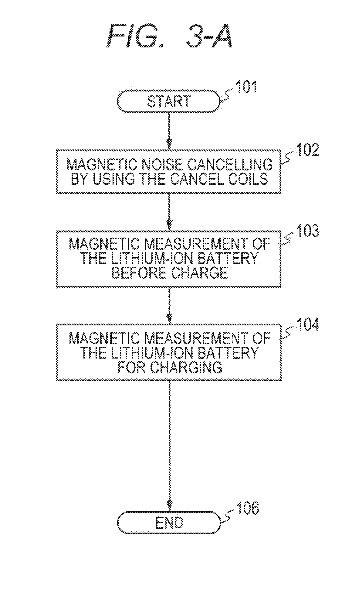
In a magnetic measurement system for a battery, a magnetic signal generated by electric currents in the battery for charging and discharging can be accurately measured without saturating the output of a magnetic sensor even in an environment having strong magnetic noise, and electric current distribution in the lithium-ion battery is visualized. Generating a antiphase magnetic field having an antiphase magnetic field to a magnetic field measured by each magnetic sensor into the cancel coil disposed around each the magnetic sensor before charging and discharging; thereafter, reducing magnetic noise by subtracting the magnetic data recorded before charging and discharging (the correction-magnetic field data) from the magnetic data for charging and discharging; and accurately measuring the magnetic signal generated from the lithium-ion battery for charging and discharging are included.

Description

CLAIM OF PRIORITY[0001]The present application claims priority from Japanese patent application JP 2011-193613 filed on Sep. 6, 2011, the content of which is hereby incorporated by reference into this application.FIELD OF THE INVENTION[0002]The present invention relates to a magnetic measurement system for batteries. The invention more particularly relates to a system and method using magnetic sensors for measuring a magnetic field generated from a battery, such as a lithium-ion battery, during charging and discharging.BACKGROUND OF THE INVENTION[0003]Recently, much attention has been attracted to electricity storage technologies including secondary batteries. For example, developments of an electricity storage system storing renewable energy such as solar power generation and wind power generation which do not generate CO2 and a storage battery for an electric vehicle, a hybrid vehicle, and a plug-in hybrid vehicle are advanced by various organizations.[0004]As the secondary batter...

Claims


Application Information

Patent Timeline
IPC IPC(8): G01R33/02G01N27/416
CPCG01R33/02
Inventor OGATA, KUNIOMIKAWABATA, RYUZOKANDORI, AKIHIROKOJIMA, KATSUNORINAGAI, RYO
Owner HITACHI LTD
Learn More