Camshaft phaser with a rotary valve spool positioned hydraulically

a technology of camshaft and spool, which is applied in the direction of liquid fuel engines, machines/engines, rotary piston liquid engines, etc., can solve the problems that the phasing oil control valve is sensitive to engine speed and the direct rotation of the phasing oil control valve is not adequate for operation

Active Publication Date: 2016-06-16
DELPHI TECH IP LTD
View PDF4 Cites 22 Cited by
  • Summary
  • Abstract
  • Description
  • Claims
  • Application Information

AI Technical Summary

Benefits of technology

[0004]Briefly described, a camshaft phaser is provided for use with an internal combustion engine for controllably varying the phase relationship between a crankshaft and a camshaft in the internal combustion engine where the camshaft phaser includes an input member which is connectable to the crankshaft of the internal combustion engine to provide a fixed ratio of rotation between the input member and the crankshaft; an output member which is connectable to the camshaft of the internal combustion engine and defining a phasing advance chamber and a phasing retard chamber with the input member; and a rotary valve spool coaxially disposed within the output member such that the rotary valve spool is rotatable relative to the output member and the input member, the valve spool defining a rotary valve spool advance chamber and a rotary valve spool retard chamber. Oil supplied to the rotary valve spool advance chamber causes the rotary valve spool to rotate relative to the output member and relative to the input member in a retard direction; oil supplied to the rotary valve spool retard chamber causes the rotary valve spool to rotate relative to the output member and relative to the input member in an advance direction; rotation of the rotary valve spool in the advance direction allows oil to be supplied to the retard chamber, thereby causing the output member to rotate relative to the input member in the advance direction; and rotation of the rotary valve spo

Problems solved by technology

Rotating the phasing oil control valve directly and mechanically by an arm that is sensitive to engine speed may not be adequate for operation because modern internal combustion engines rely on many parameter

Method used


Image

  • Camshaft phaser with a rotary valve spool positioned hydraulically
  • Camshaft phaser with a rotary valve spool positioned hydraulically
  • Camshaft phaser with a rotary valve spool positioned hydraulically

Examples


Embodiment Construction

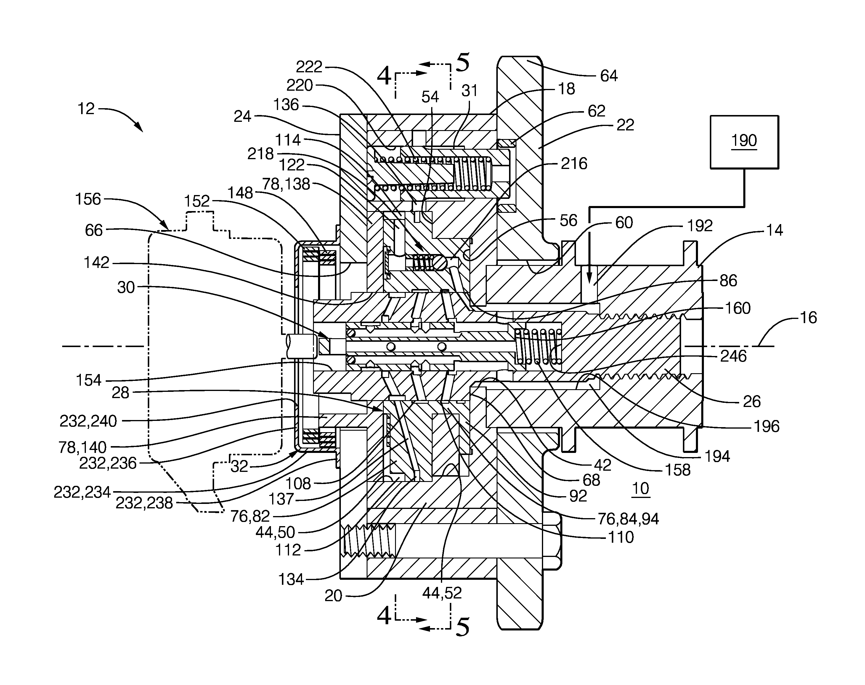
[0025]In accordance with a preferred embodiment of this invention and referring to FIGS. 1-5, an internal combustion engine 10 is shown which includes a camshaft phaser 12. Internal combustion engine 10 also includes a camshaft 14 which is rotatable about a camshaft axis 16 based on rotational input from a crankshaft and chain (not shown) driven by a plurality of reciprocating pistons (also not shown). As camshaft 14 is rotated, it imparts valve lifting and closing motion to intake and / or exhaust valves (not shown) as is well known in the internal combustion engine art. Camshaft phaser 12 allows the timing or phase between the crankshaft and camshaft 14 to be varied. In this way, opening and closing of the intake and / or exhaust valves can be advanced or retarded in order to achieve desired engine performance.

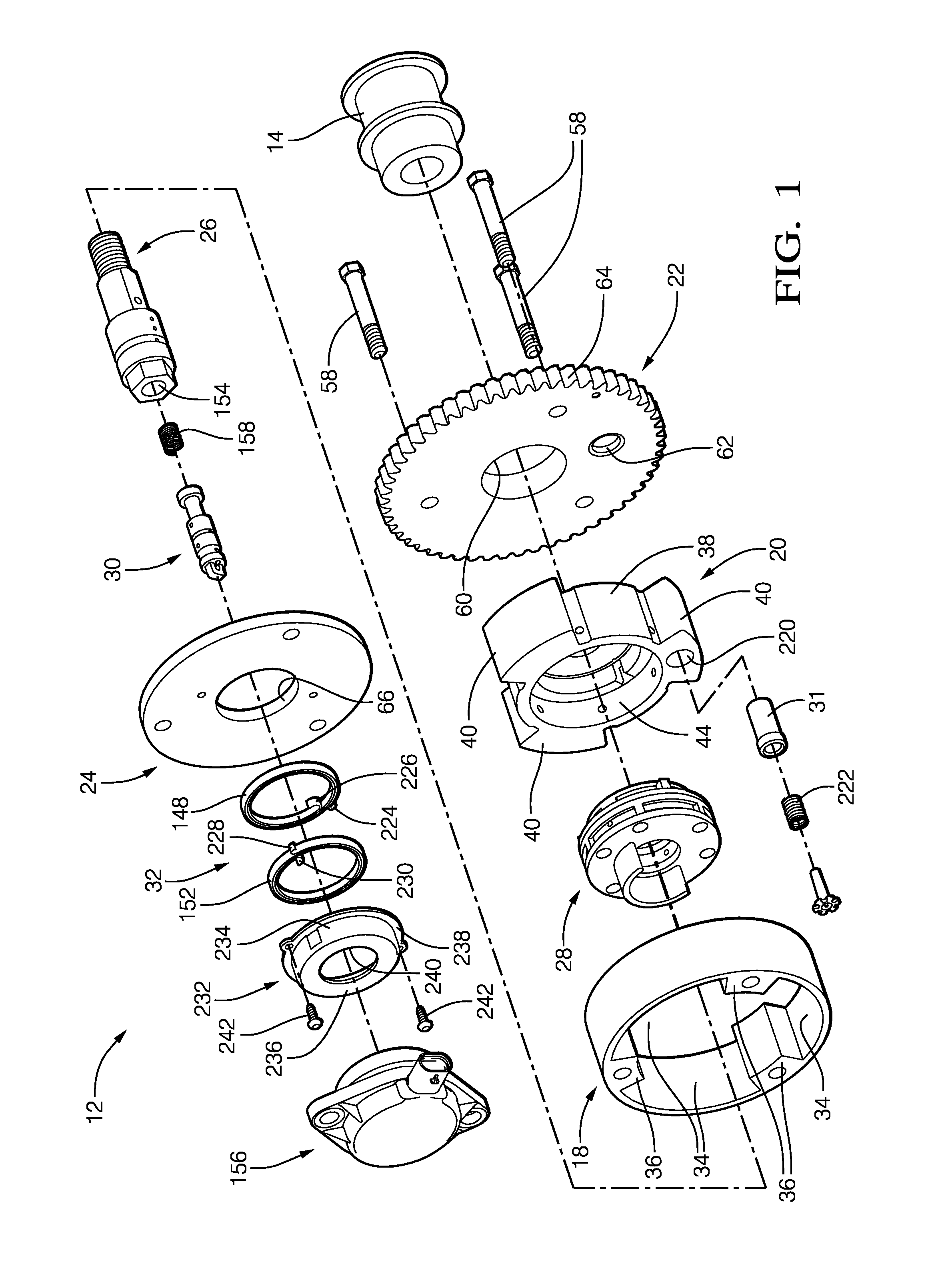
[0026]Camshaft phaser 12 generally includes a stator 18 which acts as an input member, a rotor 20 disposed coaxially within stator 18 which acts as an output member, a back cove...


PUM


Abstract

A camshaft phaser includes an input member; an output member defining a phasing advance chamber and a phasing retard chamber with the input member; and a rotary valve spool coaxially disposed within the output member such that the rotary valve spool is rotatable relative to the output member and the input member, the valve spool defining a rotary valve spool advance chamber and a rotary valve spool retard chamber. Oil supplied to the rotary valve spool advance chamber causes the rotary valve spool to rotate relative to the output member and relative to the input member in a retard direction and oil supplied to the rotary valve spool retard chamber causes the rotary valve spool to rotate relative to the output member and relative to the input member in an advance direction.

Description

TECHNICAL FIELD OF INVENTION[0001]The present invention relates to a camshaft phaser for varying the phase relationship between a crankshaft and a camshaft in an internal combustion engine; more particularly to such a camshaft phaser which is a vane-type camshaft phaser; even more particularly to a vane-type camshaft phaser which includes a rotary valve spool in which the position of the rotary valve spool determines the phase relationship between the crankshaft and the camshaft; and still even more particularly to such a camshaft phaser which uses hydraulics to position the rotary valve spool, and still yet even more particularly to such a camshaft phaser which includes a linear valve spool to control oil flow for positioning the rotary valve spool.BACKGROUND OF INVENTION[0002]Camshaft phasers are known for changing the phase relationship between a crankshaft and a camshaft in an internal combustion engine in order to achieve desired engine performance. U.S. Pat. No. 5,507,254 to M...

Claims


Application Information

Patent Timeline
IPC IPC(8): F01L1/344F04C2/344F01L1/047
CPCF01L1/3442F01L2001/34426F04C2/344F01L1/047F01L2001/3445
Inventor FISCHER, THOMAS H.HALTINER, JR., KARL J.
Owner DELPHI TECH IP LTD
Why Eureka
Try Eureka