Combustion chamber with ducts for internal combustion engines

a combustion engine and combustion chamber technology, applied in combustion engines, machines/engines, cylinders, etc., can solve the problems of inducing thermal stresses in pistons, affecting emissions, and combustion of fuel and air mixtur

Inactive Publication Date: 2016-06-16
CATERPILLAR INC
View PDF7 Cites 14 Cited by
  • Summary
  • Abstract
  • Description
  • Claims
  • Application Information

AI Technical Summary

Benefits of technology

[0005]In one aspect of the present disclosure, an internal combustion engine is provided. The internal combustion engine includes an engine cylinder, a piston, a cylinder head, a combustion chamber, and a fuel injector. The piston is disposed within the engine cylinder and adapted to perform reciprocating movement within the engine cylinder. The cylinder head is adapted to cover the engine cylinder. The cylinder head has a depress

Problems solved by technology

In the current design of combustion chambers, the combusting flame may impinge directly on the top of the piston, inducing thermal stres

Method used


Image

  • Combustion chamber with ducts for internal combustion engines
  • Combustion chamber with ducts for internal combustion engines
  • Combustion chamber with ducts for internal combustion engines

Examples


Embodiment Construction

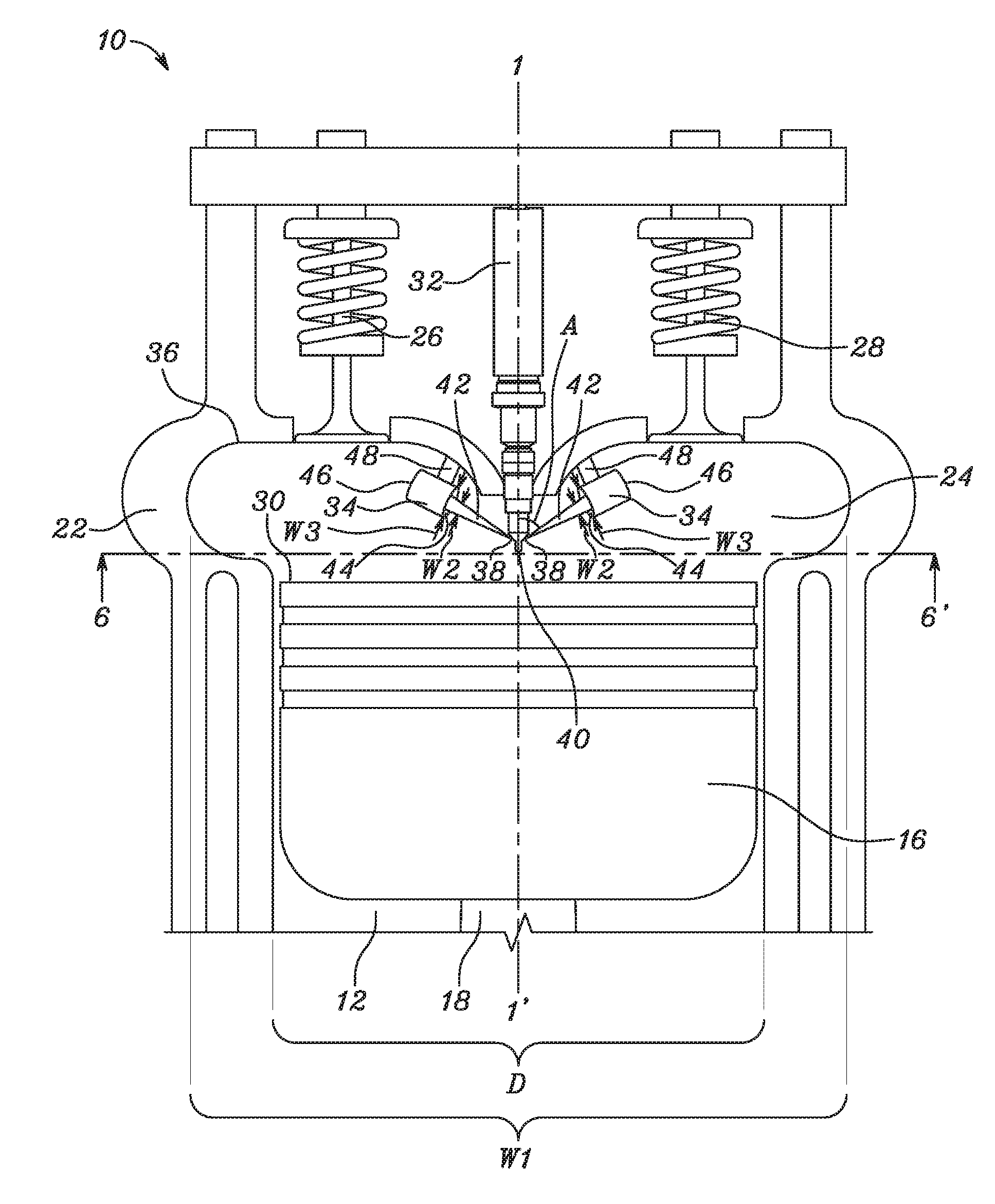
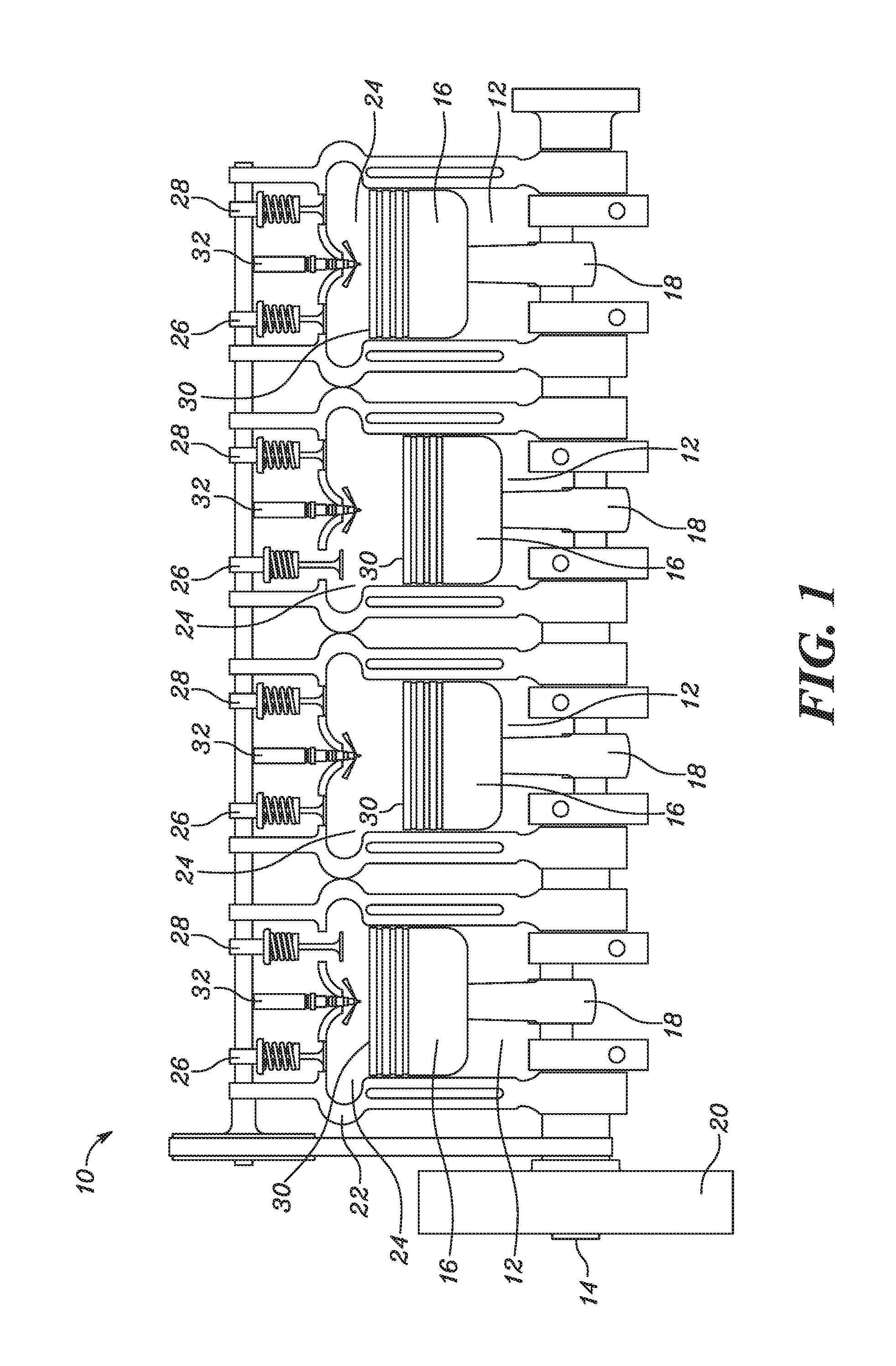
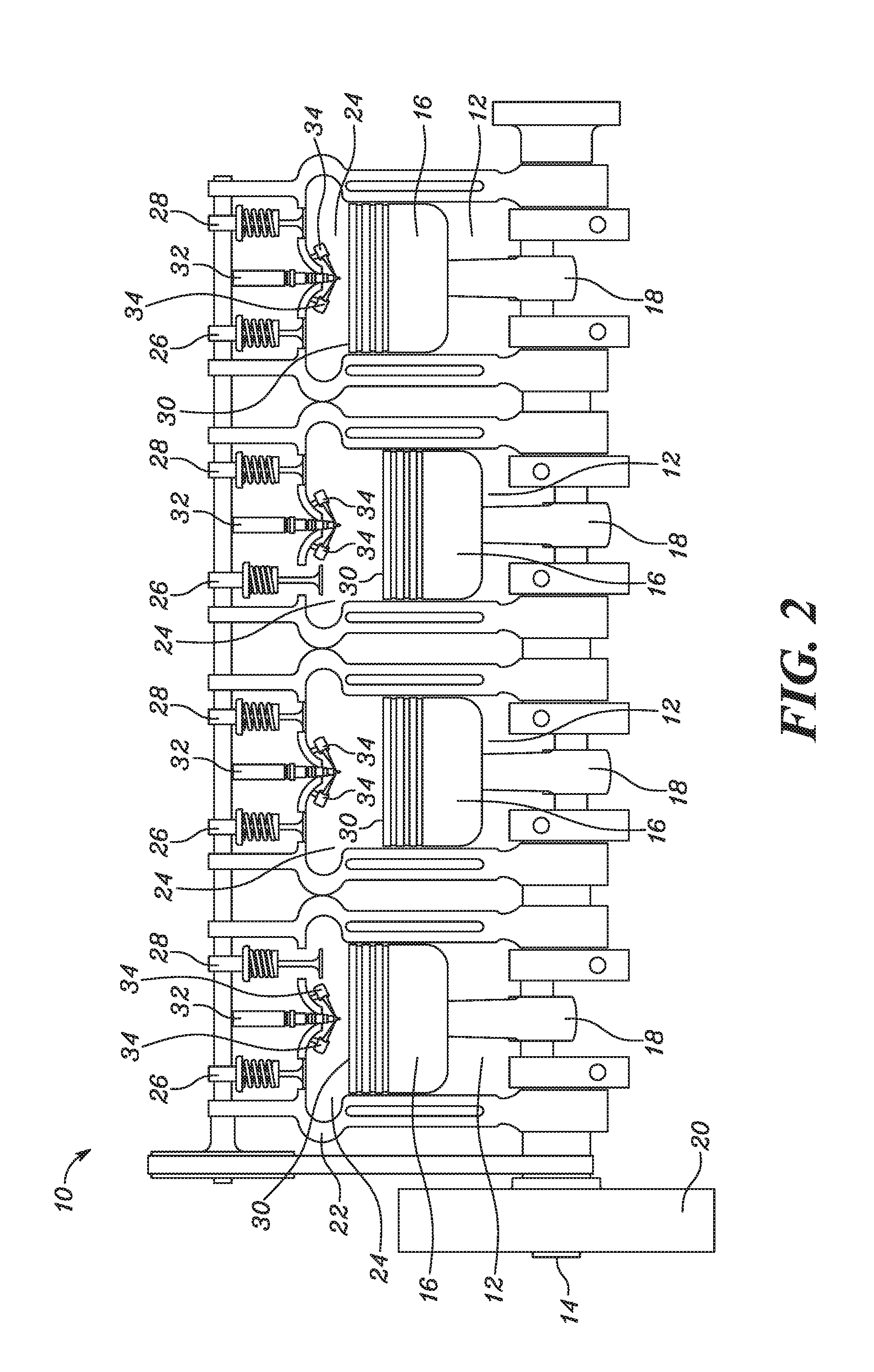
[0013]Referring to FIG. 1, an internal combustion engine 10 includes an engine cylinder 12. In an embodiment, the internal combustion engine 10 includes four engine cylinders 12. The four engine cylinders 12 are mounted in a straight line, one after another, along a crankshaft 14. The internal combustion engine 10 is provided with a piston 16 disposed within the engine cylinder 12 and is adapted to perform reciprocating movement within the engine cylinder 12. The piston 16 is connected to the crankshaft 14 via a connecting rod 18. The crankshaft 14 is coupled to a flywheel 20. The flywheel 20 imparts rotational energy to the crankshaft 14 from time to time in order to keep the crankshaft 14 rotating. The flywheel 20 may also be used as a damper to absorb torsional vibrations and to smoothen the power output of the internal combustion engine 10. It would be apparent to one skilled in the art that the internal combustion engine 10 may have any number of engine cylinders 12 for perform...


PUM


Abstract

An internal combustion engine is provided. The internal combustion engine includes an engine cylinder, a piston, a cylinder head, a combustion chamber, and a fuel injector. The cylinder head has a depression of predefined shape such that an effective width of the depression of cylinder head is greater than a diameter of the engine cylinder. The combustion chamber is defined as an enclosure between the depression of the cylinder head and a crown of the piston. The fuel injector is adapted to supply fuel to the combustion chamber via a number of orifices. In an alternate embodiment, the combustion chamber is provided with a number of ducts adapted to provide a passage to the fuel exiting from the orifices. The ducts extend at a predefined angle with an axis of the engine cylinder to facilitate injection of the fuel towards the depression of the cylinder head within the combustion chamber.

Description

TECHNICAL FIELD[0001]The present disclosure relates to a combustion chamber of an internal combustion engine, and more specifically, to the combustion chamber having a predefined shape that allows for a longer free-jet combustion duration in the internal combustion engine.BACKGROUND[0002]In general, an internal combustion engine includes a combustion chamber where a mixture of fuel and intake charge (i.e. air that may include diluents such as re-circulated exhaust gases) is ignited to produce power. The combustion chamber is generally formed by a recess in a cylinder head on one side and by a recess in a top of a piston on another side. The design of the combustion chamber has a significant impact on the thermal efficiency and emissions of the internal combustion engine.[0003]In the current design of combustion chambers, the combusting flame may impinge directly on the top of the piston, inducing thermal stresses in the piston. The piston is typically cooled to reduce the impact of ...

Claims


Application Information

Patent Timeline
IPC IPC(8): F02B23/02
CPCF02B23/02F02F1/24Y02T10/12
Inventor SVENSSON, KENTH I.
Owner CATERPILLAR INC
Why Eureka
Try Eureka