
Light emitting diode apparatus, system, and method

a technology of light-emitting diodes and apparatuses, applied in the field of illumination devices, can solve problems such as uneven light intensity distribution, and achieve the effect of reducing or eliminating the risk of shock

Inactive Publication Date: 2016-06-16
NUWAVE
View PDF5 Cites 6 Cited by
  • Summary
  • Abstract
  • Description
  • Claims
  • Application Information

AI Technical Summary

Benefits of technology

The patent text describes a LED bulb that is designed to prevent shock risks by filling any air gaps with silicone and isolating the electronic components on the AC side of the inverter. This results in a safer and more reliable LED bulb.

Problems solved by technology

When the plurality of LEDs are arranged on the planar, light may be produced in typically one direction, which may result in uneven light intensity distribution.

Method used


Image

  • Light emitting diode apparatus, system, and method
  • Light emitting diode apparatus, system, and method
  • Light emitting diode apparatus, system, and method

Examples


Embodiment Construction

Exemplary Embodiments

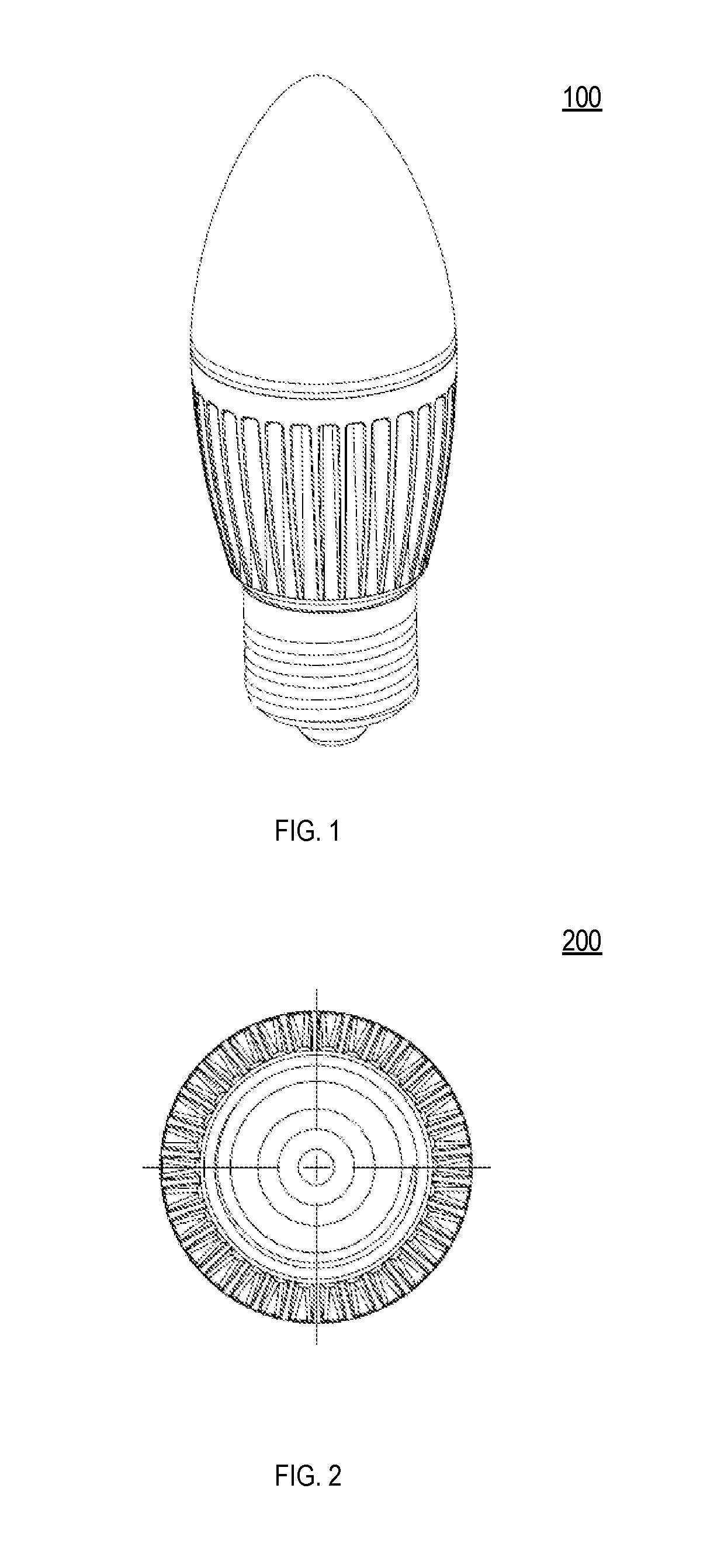
[0183]FIG. 1 is an exemplary view 100 of an exemplary isometric perspective view of an exemplary candle light bulb, with exemplary standard light socket, according to an exemplary embodiment of the present invention.

[0184]FIG. 2 is an exemplary bottom orthographic view 200 of the exemplary candle light bulb according to an exemplary embodiment of the present invention.

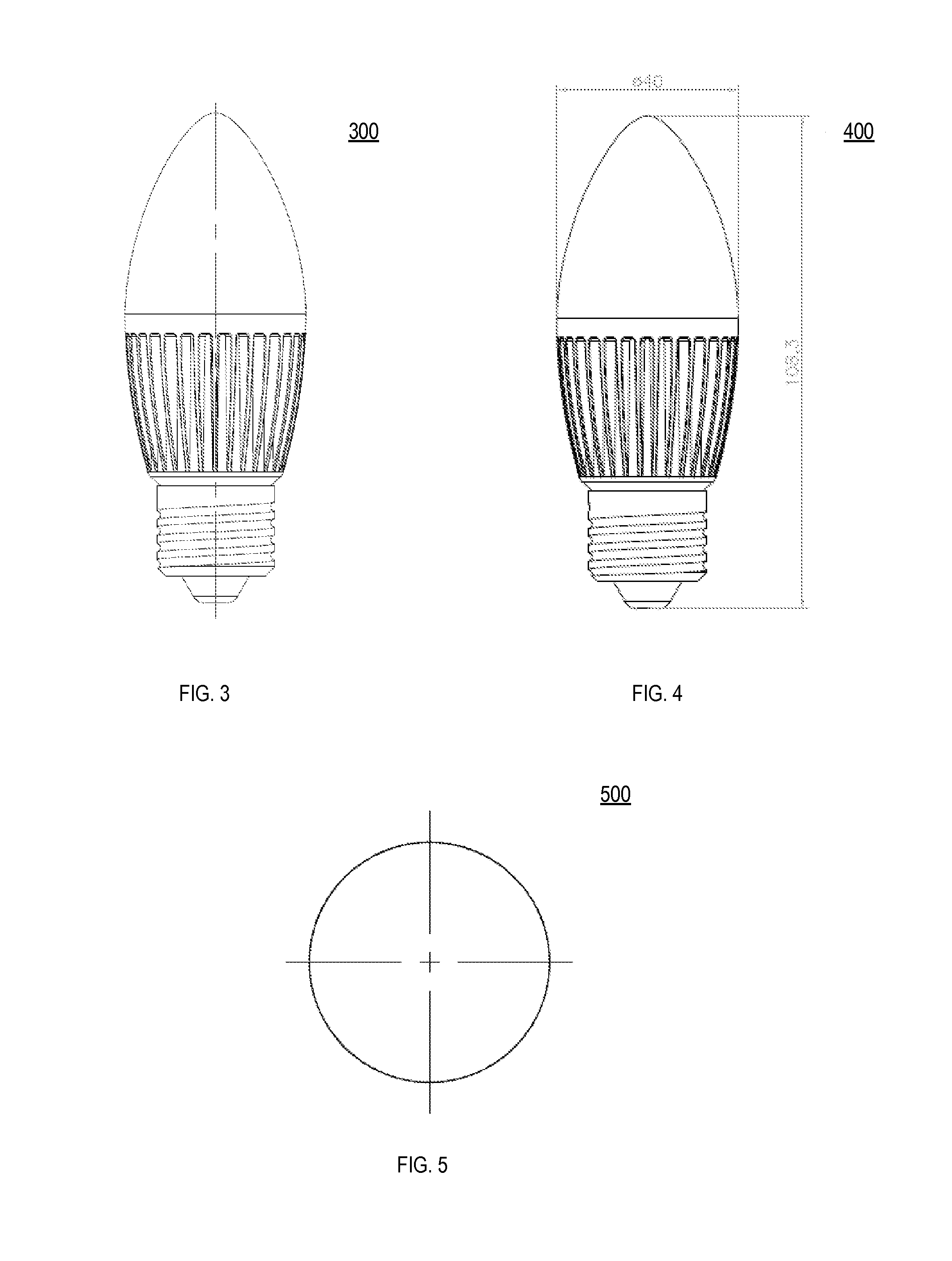
[0185]FIG. 3 is an exemplary side orthographic view 300 of the exemplary candle light bulb according to an exemplary embodiment of the present invention.

[0186]FIG. 4 is an exemplary side orthographic view 400 of the exemplary candle light bulb with exemplary nonlimiting dimensions according to an exemplary embodiment of the present invention.

[0187]FIG. 5 is an exemplary orthographic top view of the exemplary candle light bulb according to an exemplary embodiment of the present invention.

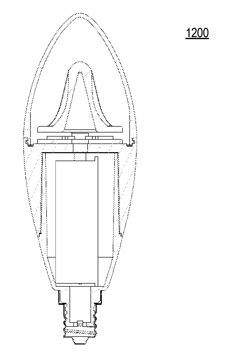
[0188]FIG. 6A is an exemplary partial cutaway cross-sectional view 600 of the exemplary candle light bulb with st...


PUM

PropertyMeasurementUnit
angleaaaaaaaaaa
color temperatureaaaaaaaaaa

Abstract

This patent discloses various exemplary light emitting diode (LED) bulb apparatus, systems and methods, including features isolating electrical components.

Description

CROSS-REFERENCE TO RELATED APPLICATIONS[0001]This application is a US Provisional Utility patent application, and is a continuation-in-part of, and claims priority under 35 USC Section 120 of U.S. Design patent application Ser. No. 29 / 484,775, filed Mar. 12, 2014, entitled “Light Bulb,” the contents of which is incorporated herein by reference in its entirety.BACKGROUND OF THE INVENTION[0002]1. Field of the Invention[0003]The present invention relates generally to illumination devices, and more particularly to a light emitting diode (LED) bulb, wherein the LED bulb has various improvements over conventional light bulbs.[0004]2. Related Art[0005]LEDs are solid state light emitting devices formed of semiconductors, which are more stable and reliable than other conventional light sources such as incandescent bulbs. LEDs are conventionally widely used in various fields such as alphanumeric display elements, signal lights, light sources for lighting, and display devices.[0006]A conventio...

Claims


Application Information

Patent Timeline
Patent Type & Authority Applications(United States)
IPC IPC(8): F21K99/00B29C70/80F21V29/503F21V29/70H05B33/08H05B37/02H05B44/00
CPCF21K9/13H05B33/0845H05B37/0272F21K9/17F21V29/503B29L2031/747B29C70/80F21Y2101/02F21Y2103/003F21Y2105/001B29K2083/00F21V29/70F21Y2105/10F21K9/232F21Y2103/10F21Y2115/10F21Y2107/40H05B41/2928F21K9/66F21K9/275H05B45/00H05B45/10H05B47/19Y02B20/00H05B45/325H05B45/12H05B47/1965H05B47/1985
Inventor MOON, JUNG SIKCHA, EUNG YUBHUH, EUNJUNG
Owner NUWAVE
Learn More