Time Synchronization Control Apparatus And Method

a control apparatus and time synchronization technology, applied in the direction of electromechanical clocks, instruments, electronic time-pieces, etc., can solve the problems of manmade and natural interference, and the criticality of clock synchronization errors of this nature, so as to avoid the vulnerability experienced

Inactive Publication Date: 2016-06-16
THE UK SEC FOR BUSINESS INNOVATION & SKILLS OF HER MAJESTYS BRITTANNIC GOVERNMENT
View PDF10 Cites 9 Cited by
  • Summary
  • Abstract
  • Description
  • Claims
  • Application Information

AI Technical Summary

Benefits of technology

The patent describes a system that can provide accurate and predictable synchronized clock signals to multiple remote stations. This system is closed loop, meaning that a reference station controls the time indicator at each remote station. This ensures that the local time clocks of the remote stations are synchronized, regardless of their individual connection latencies. The system is robust and secure, with a direct cable link between the reference station and the remote stations. The reference station calculates the synchronized time signal for each remote station, taking into account the latencies introduced by each component of the receiver chain. This eliminates the need for the remote stations to calculate the synchronized time signal themselves, which could result in inaccuracies.

Problems solved by technology

The technical problem addressed in this patent text relates to the need for accurate timing in various transactions and processes, especially at a global level where synchronization between different users becomes crucial. However, current methods like GPS may face issues with interference and latency, leading to errors in clock synchronization of up to 1 millionth of a second. These errors can impact numerous industries including finance, auditing, and research, making it necessary to find better ways to achieve precise timestamps.

Method used


Image

  • Time Synchronization Control Apparatus And Method
  • Time Synchronization Control Apparatus And Method
  • Time Synchronization Control Apparatus And Method

Examples


Embodiment Construction

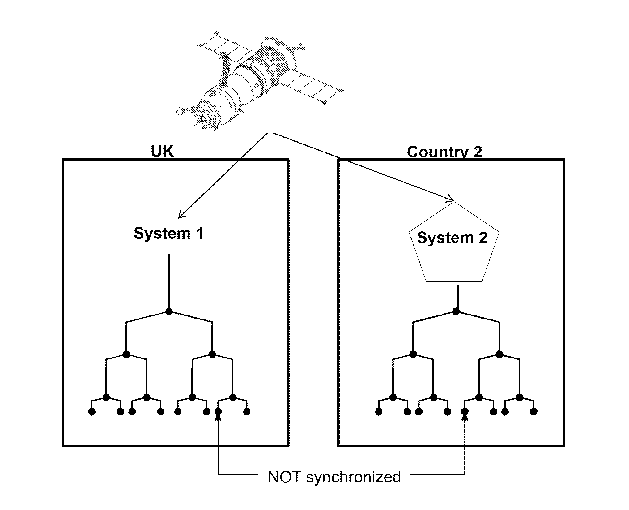
[0024]Referring first to FIG. 1, this shows in schematic form an example of the existing apparatus and arrangement for providing synchronized clock signals at separate locations.

[0025]A first system (system 1) provides a reference clock signal to a plurality of local users, shown as the nodes in the left-hand box in FIG. 1. Synchronization of physically separated and unconnected networks, for example in a second country, is carried out using GPS. In this case, the system uses GPS time as the single source for each network and the Universal Time Clock. This is viable but is vulnerable to manmade and natural interferences such as jamming, spoofing, meaconing and solar storms. Additionally, the latencies introduced by each component of the receiver chain, namely antennas, cables, amplifiers, distribution systems and receivers, require careful calibration in order to understand the traceability offsets that are implemented.

[0026]Synchronization requirements on a global scale are becomin...


PUM


Abstract

A local clock network can have a reference control unit with a reference clock. Coupled to each reference clock can be a plurality of remote stations. User units are in the form of clock indicator units which provided clock signals for use by internal client systems. The network(s) is/are closed loop system(s) between the associated reference and remote user stations. Each reference station determines the latency associated with each remote user station and generates an offset for each user station. Each reference station then generates a specific clock signal for each remote user station on the basis of its reference clock signal adjusted by the appropriate user station offset. A plurality of separate networks can be synchronized by reference to their local Coordinated Universal Time clocks, with one reference station acting as a master station.

Description


Claims


Application Information

Patent Timeline
Owner THE UK SEC FOR BUSINESS INNOVATION & SKILLS OF HER MAJESTYS BRITTANNIC GOVERNMENT
Why Eureka
Try Eureka