

Organic electroluminescent element and illumination device
- Summary
- Abstract
- Description
- Claims
- Application Information
AI Technical Summary
Benefits of technology
Problems solved by technology
Method used
Image

Examples
first embodiment
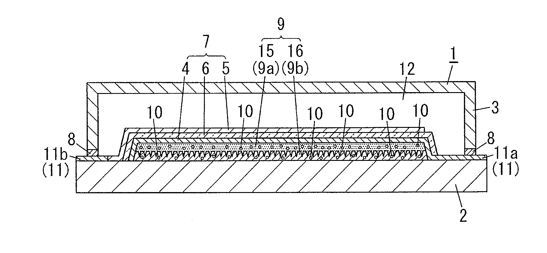
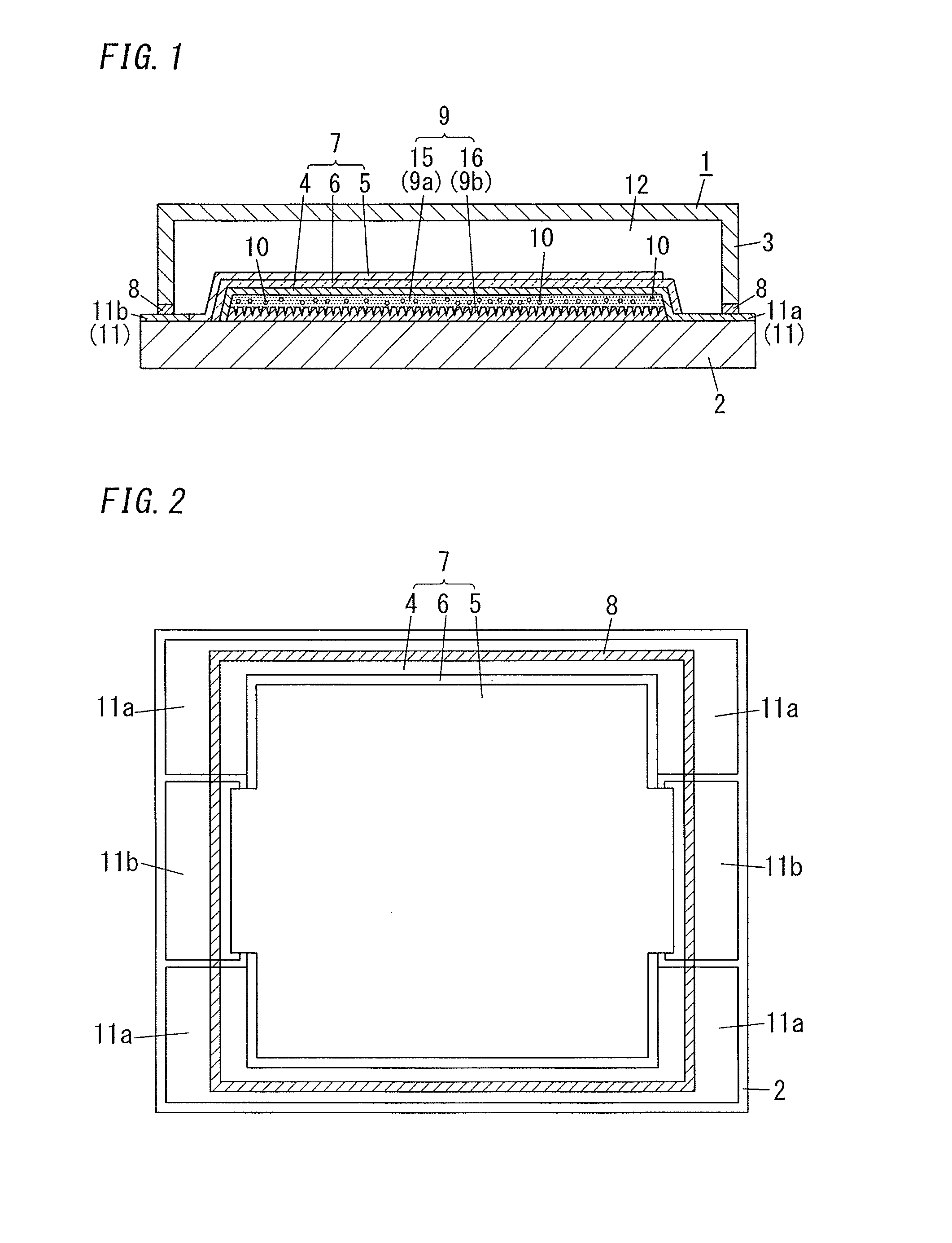
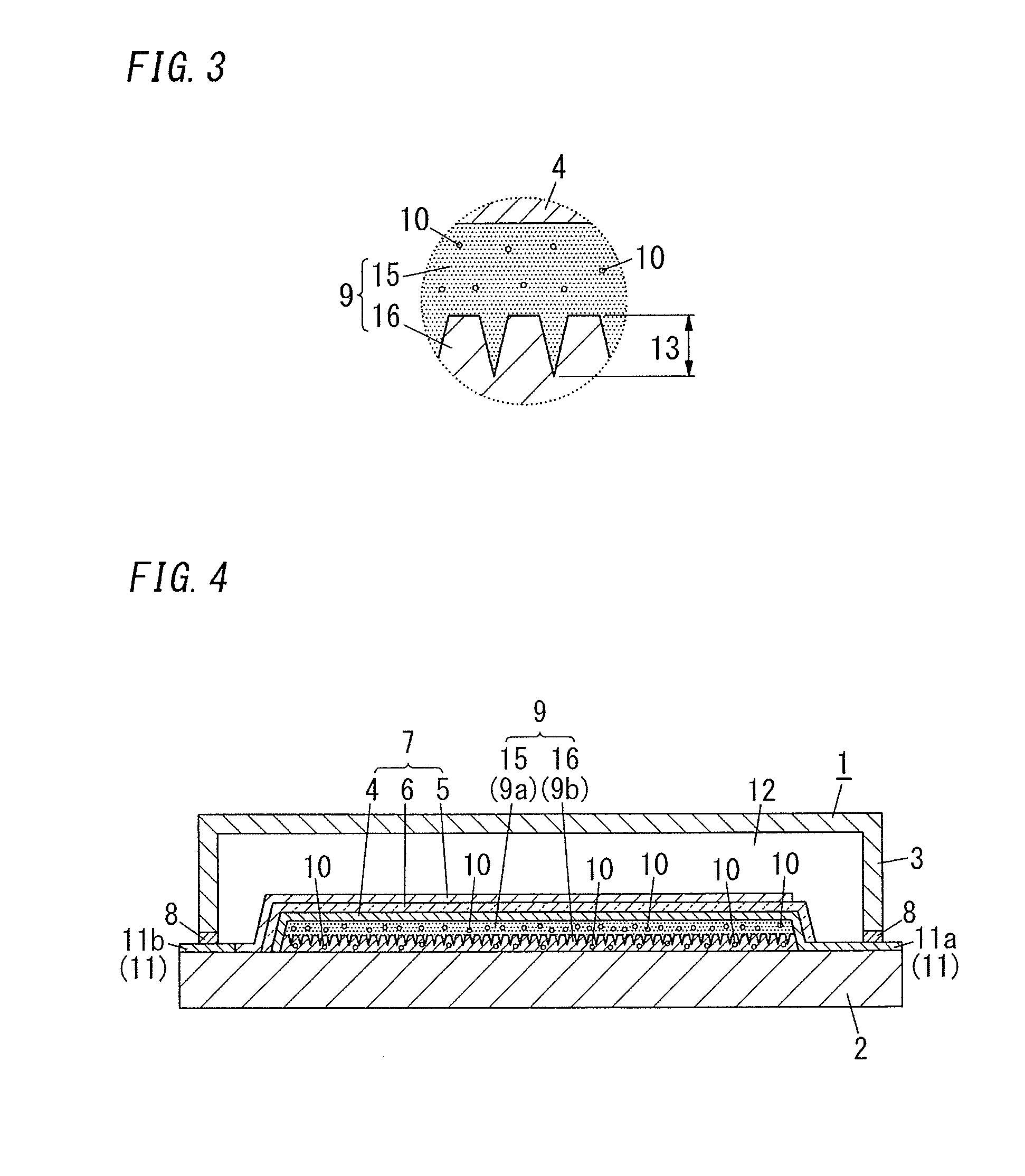
[0020]FIG. 1 illustrates an organic electroluminescent element (organic EL element) of the first embodiment. The organic EL element 1 includes: a light transmissive substrate 2; a light transmissive electrode 4; a counter electrode 5 paired with the light transmissive electrode 4; a sealing substrate 3 facing the light transmissive substrate 2; an organic light-emitting layer 6; and a resin structure 9. The organic light-emitting layer 6 is disposed between the light transmissive electrode 4 and the counter electrode 5. The organic light-emitting layer 6 is sealed with the light transmissive substrate 2 and the sealing substrate 3. The resin structure 9 is disposed between the light transmissive electrode 4 and the light transmissive substrate 2. The resin structure 9 is composed of a plurality of resin layers including a high refractive index layer 15 and a low refractive index layer 16 with different refractive indices. The high refractive index layer 15 contains a physisorption-b...
second embodiment
[0063]FIG. 4 illustrates an organic EL element of the second embodiment. The second embodiment differs from the first embodiment in terms of the low refractive index layer 16 and otherwise both embodiments may be same. Same components as in the first embodiment are referred to the same signs and explanation is omitted.
[0064]In the organic EL element 1 of the second embodiment, a moisture-absorbing material 10 is contained in both of a high refractive index layer 15 and a low refractive index layer 16. When the moisture-absorbing material 10 is also contained in the low refractive index layer 16, moisture absorptivity is increased and deterioration of the element is further prevented.
[0065]The moisture-absorbing material 10 contained in the low refractive index layer 16 may or may not be same as the moisture-absorbing material 10 contained in the high refractive index layer 15. When the same moisture-absorbing material 10 is contained, the number of materials can be reduced. When the...
third embodiment
[0068]FIG. 5 illustrates an organic EL element of the third embodiment. The third embodiment differs from the first embodiment in terms of the resin structure 9 and otherwise both embodiments may be same. Same components as in the first embodiment are referred to the same signs and explanation is omitted.
[0069]In the organic EL element 1 of the third embodiment, a resin structure 9 includes an adhesion layer 14 to increase adhesiveness between the resin structure 9 and a light transmissive substrate 2. The adhesion layer 14 is disposed closer to the light transmissive substrate 2 in the resin structure 9.
[0070]In the organic EL element 1, when thermal stress differs between the plurality of layers stacked on the light transmissive substrate 2, peeling and cracks may tend to occur at the layer interface. Especially, in manufacturing the organic EL element 1, following the formation of the resin structure 9, a light transmissive electrode 4 and an organic light-emitting layer 6 might ...
PUM
 Abstract
Description
Claims
Application Information