In-situ interlocking of metals using additive friction stir processing

a technology of additive friction stir and interlocking metals, which is applied in the direction of furniture joining, non-electric welding apparatus, fastening means, etc., can solve the problems of large portion of the substrate to soften, the thickness of the material, and the inability of conventional techniques to bond dissimilar materials such as steel and aluminum

Active Publication Date: 2016-06-23
MELD MFG CORP
View PDF14 Cites 27 Cited by
  • Summary
  • Abstract
  • Description
  • Claims
  • Application Information

AI Technical Summary

Benefits of technology

[0016]The methods of the invention are useful for creating a variety of composite materials with layers of dissimilar composition and properties. Practical applications of these composite materials include use as components for manufacturing automobiles, ships, tanks, planes, and aerospace vehicles.

Problems solved by technology

Frictional heat produced between the substrate and the tool during the process causes the opposed portions of the substrate to soften, and mechanical intermixing and pressure cause the two materials to join.
Conventional techniques are incapable of bonding dissimilar materials such as steel and aluminum.
This method has numerous limitations related to material pairing, thickness and the environment in which it is conducted.

Method used


Image

  • In-situ interlocking of metals using additive friction stir processing
  • In-situ interlocking of metals using additive friction stir processing
  • In-situ interlocking of metals using additive friction stir processing

Examples


example

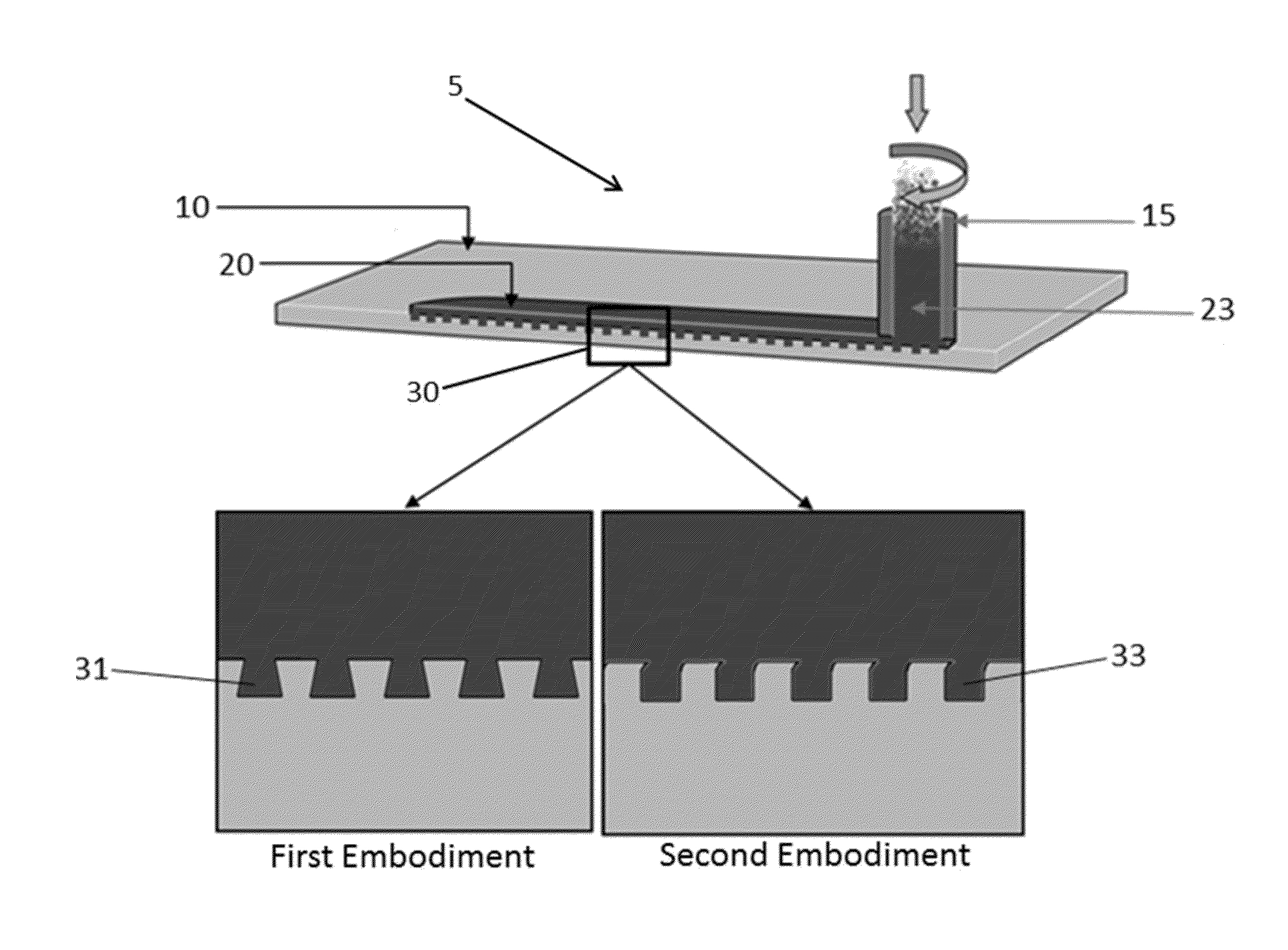
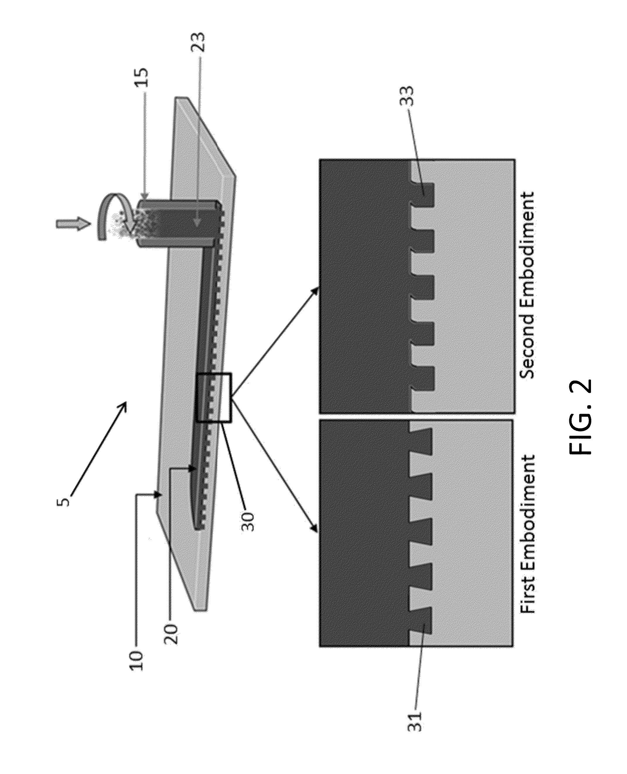
[0065]FIG. 4 is a macrograph image showing a cross section of an article of manufacture comprising two different metals (molybdenum and copper) in an interlocking configuration prepared according to an embodiment of the invention. The substrate comprises molybdenum and multiple grooves in the surface of the substrate. The cross-sectional shape of the grooves in the substrate is rectangular. Copper was added to the surface of the substrate using an additive friction stir tool. At least one side of the grooves was deformed during the additive friction stir process to provide for a mechanical interlocking configuration between the molybdenum substrate and the copper coating. In the area of the joint between the molybdenum and copper, each of the copper and molybdenum have two-dimensional projections into this area as shown. Some of the two-dimensional projections are of convex polygon shape and some are of concave polygon shape. Other combinations of materials can also be used, includi...


PUM

PropertyMeasurementUnit
widthaaaaaaaaaa
widthaaaaaaaaaa
depthaaaaaaaaaa

Abstract

A method for joining materials using additive friction stir techniques is provided. The method joins a material to a substrate, especially where the material to be joined and the substrate are dissimilar metals. One such method comprises (a) providing a substrate with one or more grooves; (b) rotating and translating an additive friction-stir tool relative to the substrate; (c) feeding a filler material through the additive friction-stir tool; and (d) depositing the filler material into the one or more grooves of the substrate. Translation and rotation of the tool causes heating and plastic deformation of the filler material, which flows into the grooves of the substrate resulting in an interlocking bond between the substrate and filler material. In embodiments, the depositing of the filler material causes deformation of the grooves in the substrate and an interlocking configuration between the grooves of the substrate and the filler material results.

Description

CROSS-REFERENCE TO RELATED APPLICATIONS[0001]The present application is a Continuation-in-Part (CIP) of U.S. patent application Ser. No. 14 / 573,430 filed Dec. 17, 2014, the disclosure of which is incorporated herein by reference in its entirety.BACKGROUND OF THE INVENTION[0002]1. Field of the Invention[0003]The present invention is in the field of solid state materials joining. In particular the invention is in the field of joining, coating, or cladding of metals, such as two dissimilar or incompatible materials that are not typically recommended for conventional coating or cladding or joining.[0004]2. Description of Related Art[0005]Friction-stir processing provides for the solid state joining of pieces of metal at a joint region through the generation of frictional heat at the joint and opposed portions of the metal pieces by cyclical movements of a tool piece that is harder than the metal pieces. An example of this is provided by International Application Publication No. PCT / GB19...

Claims


Application Information

Patent Timeline
Patent Type & Authority Applications(United States)
IPC IPC(8): B23K20/12B23K20/227B23K20/233
CPCB23K20/1215B23K2203/15B23K20/128B23K20/127B23K20/129B23K20/2333B23K20/2275B23K20/227B23K2203/20B23K2203/22B23K2203/24B23K2203/26B23K2203/18B23K2203/02B23K2203/10B23K2203/12B23K2203/14B23K20/1205B32B15/01B23K2103/08B23K2103/15B23K2103/18B23K2103/26B23K2103/166B23K20/1245B23K20/1265B23K20/1295B32B3/30B32B7/04B32B2250/02B32B2307/54B32B2605/08B32B2605/12B32B2605/18B33Y10/00B33Y80/00B23K2103/02B23K2103/10B23K2103/12B23K2103/14B23K2103/20B23K2103/22B23K2103/24
Inventor KANDASAMY, KUMARSCHULTZ, JEFFREY PATRICK
Owner MELD MFG CORP
Why Eureka
Try Eureka