Light emitting device

Active Publication Date: 2016-06-23
SIGNIFY HLDG BV
View PDF27 Cites 5 Cited by
  • Summary
  • Abstract
  • Description
  • Claims
  • Application Information

AI Technical Summary

Benefits of technology

[0007]It is an object of the present invention to overcome this problem, and to provide a light emitting device with which the light guide unit of the light emitting device may cover the total light emitting area of the light s

Problems solved by technology

However, the maximum possible bending of the light guide without light leakage occurring is restricted.
For light sources which have a relatively large emitting area compared to the total available space in the light emitting device the limitations

Method used


Image

  • Light emitting device
  • Light emitting device
  • Light emitting device

Examples


second embodiment

[0061]Turning now to FIG. 4, a lamp 101 employing a light emitting device 1 according to the invention is shown. The light emitting device 1 is mounted on a base 12 comprising a thread 13 for mounting the lamp 101 in a suitable socket.

[0062]As illustrated the light emitting device 1 shown in FIG. 4 comprises as light sources a plurality of LEDs 21, 22, 23 arranged in a ring with a relatively large central opening. Thus, the light guide unit, which is preferably rotational symmetric and has an overall tube-like shape with an outwardly bent part near the light output end surface 7, is likewise ring shaped in cross section with an equally large central opening.

[0063]Furthermore, the lamp 101 may be a light bulb comprising an outer cover or outer bulb (not shown), which is preferably made of a glass but may also be made of PC or PMMA or PUR or PET, and which may be diffuse or clear.

[0064]However, when the light emitting end surface 7 of the light guide unit becomes large in diameter it ...

third embodiment

[0066]With reference now to FIG. 5, a light bulb 102 employing a light emitting device 1 according to the invention is shown. The light emitting device 1 is mounted on a base 12 comprising a thread 13 for mounting the lamp 102 in a suitable socket. Furthermore, the lamp 102 comprises an outer cover or outer bulb 11, which is preferably made of a glass (but also plastic is possible), and which may be diffuse or clear.

[0067]In this embodiment, the light emitting device 1 is provided with a more filament-like look, as the light output end surface 7, and optionally also the part of the light guide unit adjacent thereto, of the light guide unit is provided with a wave shape. By changing the amplitude and frequency of such a wave shape the light distribution can also be tuned.

[0068]Furthermore, although not shown on FIG. 5, small prism structures may be provided at the light output end surface 7 of the light guide unit such as to provide for an enhanced sparkle effect. In an alternative s...

fourth embodiment

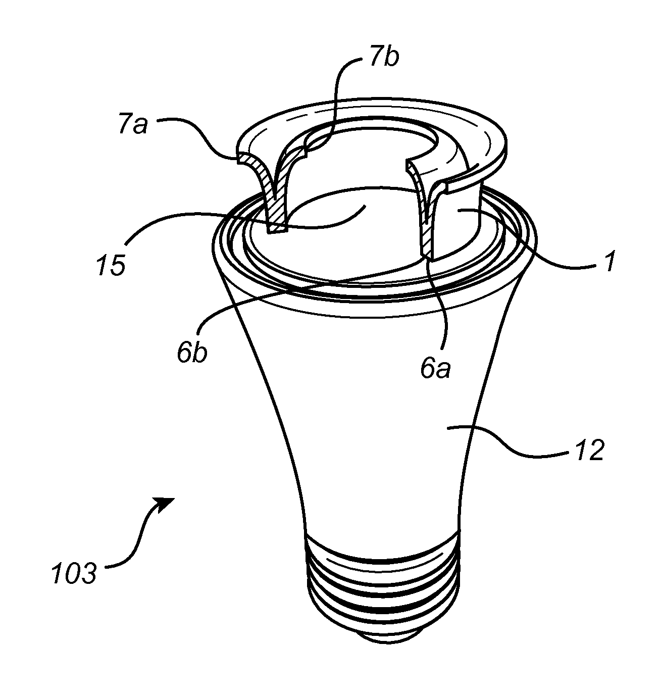
[0069]Finally, FIG. 6 shows a lamp 103 employing a light emitting device 1 according to the invention. The light emitting device 1 is mounted on a base 12, which may comprise a thread (not shown) for mounting the lamp 103 in a suitable socket. Furthermore, the lamp 103 comprises an outer cover or outer bulb (not shown), which is preferably made of a glass, and which may be diffuse or clear.

[0070]In this embodiment the light guide unit is funnel-shaped in cross section and is two-sided, i.e. it is provided with two light output end surfaces 7a, 7b, and therefore likewise with two light input end surfaces 6a, 6b. Alternatively, the light guide unit may comprise only one light input end surface, and the light guide(s) of the light guide unit may then be bifurcated to provide two light output end surfaces. That is, the light input end surfaces 6a, 6b of the two light guides are merged into one light input end surface.

[0071]In this embodiment it becomes possible to employ a thicker light...


PUM


Abstract

A light emitting device (1) comprising at least one light source (2), and a light guide unit comprising at least a first light guide (3) and a second light guide (4) each comprising a light input end surface (6, 31, 41) arranged to, when in operation, receive light emitted from the at least one light source and a light output surface (7, 32, 42), at least a part (8) of the first light guide and the second light guide near the light output end surface being bent in a bending radius (R), at least the first light guide of the light guide unit being ring-shaped in cross section, and the first light guide and the second light guide of the light guide unit being arranged in a nested relationship.

Description

FIELD OF THE INVENTION[0001]The invention relates to a light emitting device comprising at least one light source and a light guide unit comprising at least two light guides.BACKGROUND OF THE INVENTION[0002]In prior art light emitting devices it is known to use LEDs to facilitate putting light guides close to the light emitting area of the light source of the light emitting device to obtain a high coupling efficiency. For LEDs with primary lenses a side reflector is necessary for obtaining high coupling efficiencies.[0003]With flat emitting sources such as Medium Power LEDs and flat (remote) Phosphor modules it is possible to put light guides very close to the emitting surface with high coupling efficiencies.[0004]Going from a flat PCB with lambertian light sources to a more all around light emission and at the same time moving the emitting surface upwards for a better filament like look and feel it is necessary to bend the light guide. A prior art light emitting device with a light...

Claims


Application Information

Patent Timeline
IPC IPC(8): F21K99/00F21V8/00
CPCF21K9/52G02B6/0045F21Y2101/02F21K9/135G02B6/0076
Inventor ANSEMS, JOHANNES PETRUS MARIABUKKEMS, PETER JHHANNES MARTISCARIA, ABRAHAM VAMATTATHIL
Owner SIGNIFY HLDG BV
Why Eureka
Try Eureka