Dual heater system for spray dispenser

Active Publication Date: 2016-06-30
GRACO INC
View PDF2 Cites 26 Cited by
  • Summary
  • Abstract
  • Description
  • Claims
  • Application Information

AI Technical Summary

Benefits of technology

[0004]A mobile spray dispenser comprises a fluid circulation system and a heating unit. The fluid circulation system has a motorized pump capable of circulating fluid from a fluid reservoir in a high-pressure spray mode and a low-pressure recirculation mode, and of providing the fluid to a spray applicator. The motorized pump draws lower power in the low-pressure recirculation mode than in the high-pressure spray mode. Th

Problems solved by technology

Both heaters and pumps

Method used


Image

  • Dual heater system for spray dispenser
  • Dual heater system for spray dispenser
  • Dual heater system for spray dispenser

Examples


Embodiment Construction

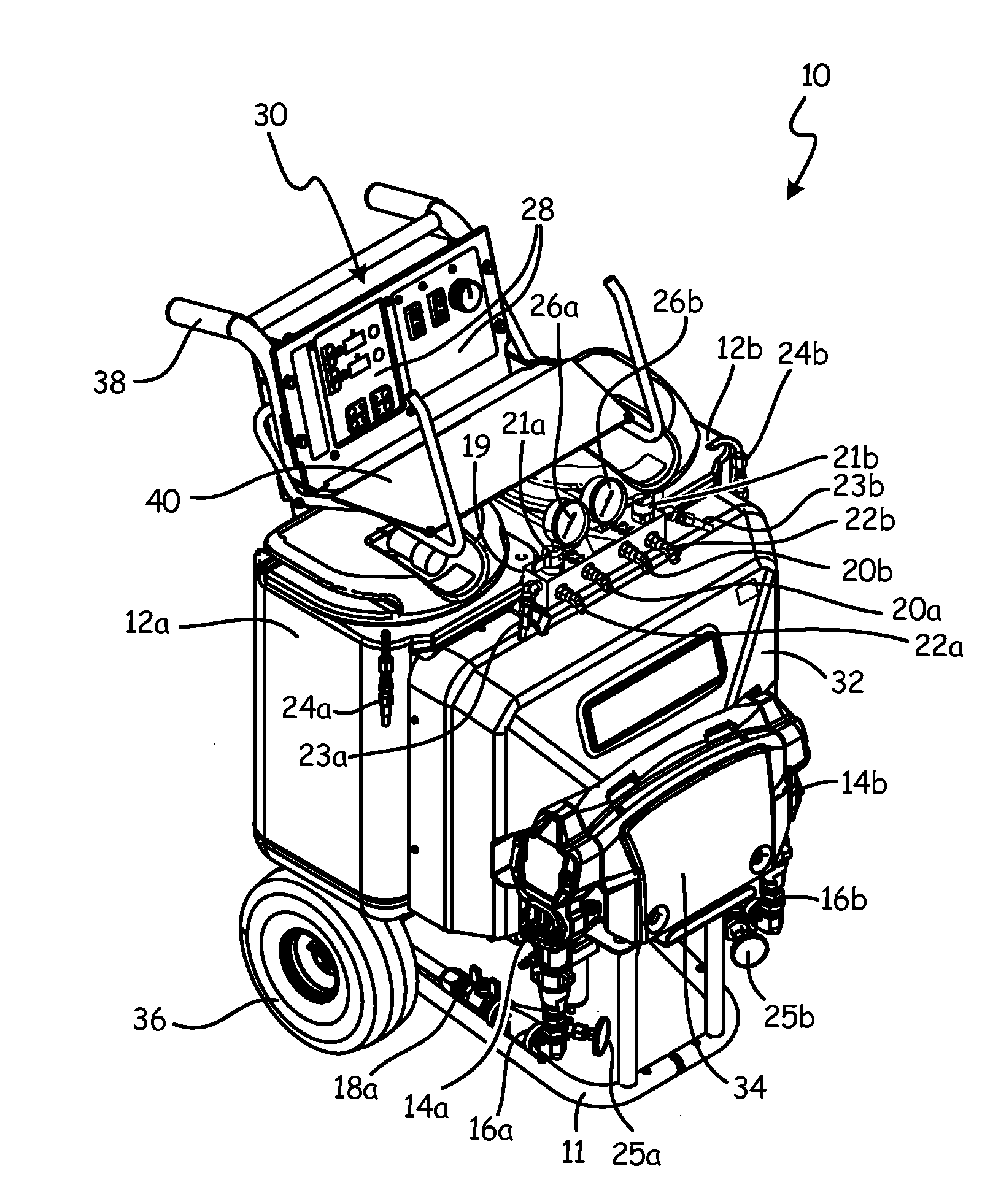
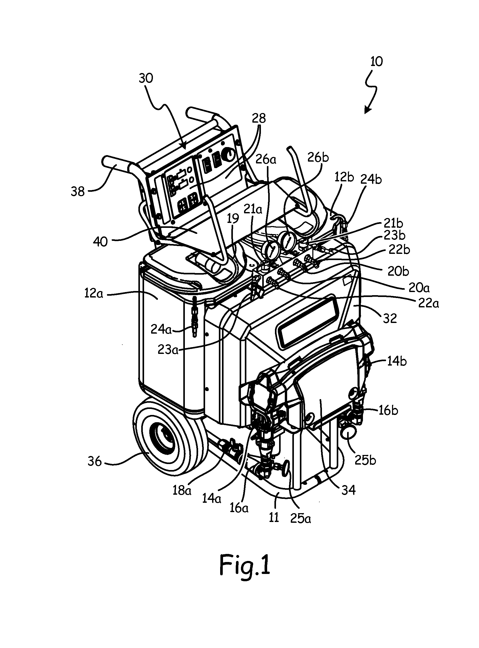
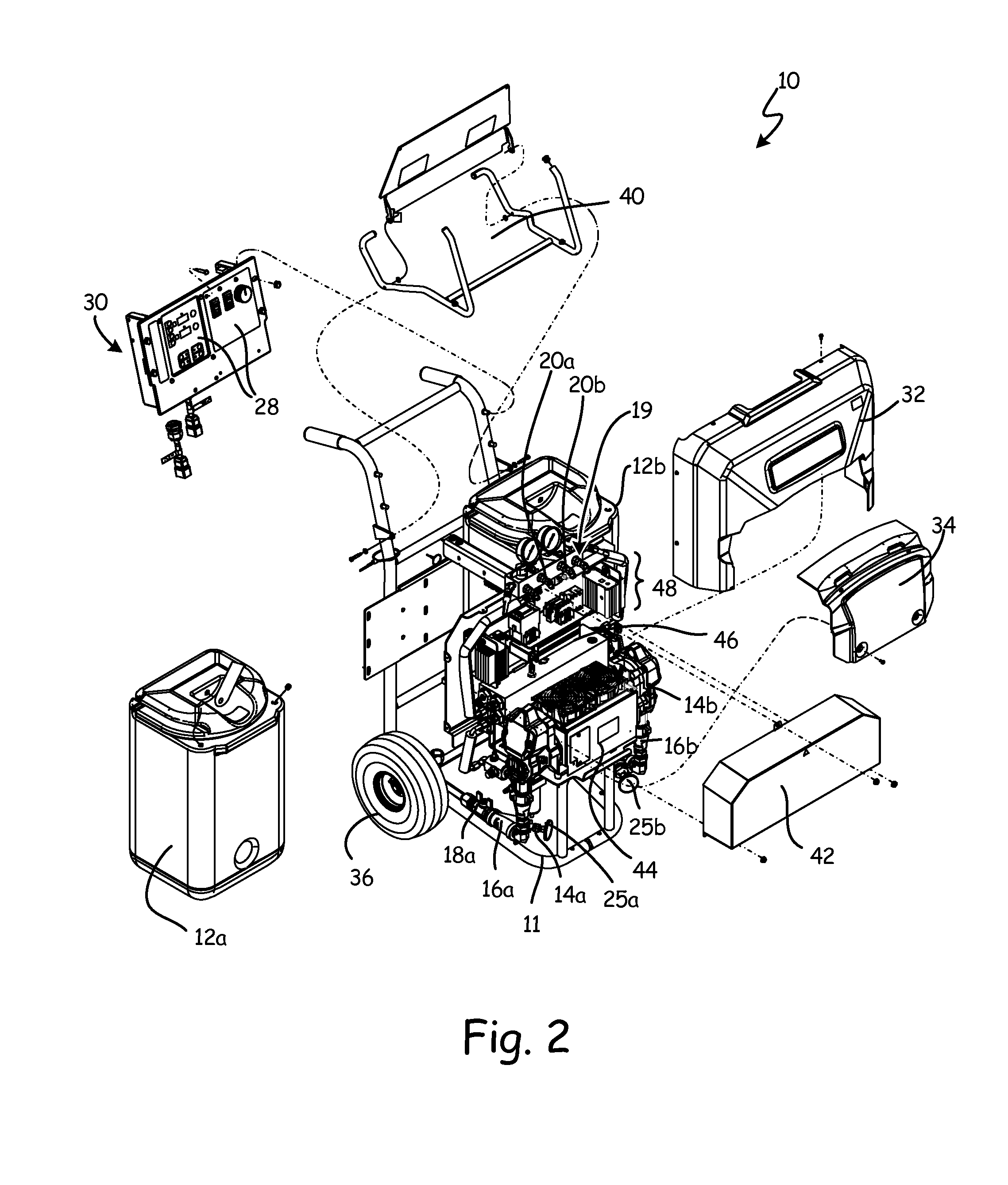
[0011]FIGS. 1 and 2 are perspective and exploded perspective views, respectively, of spray dispenser 10. Spray dispenser 10 is a mobile applicator, e.g. for polyurethane foam or polyurea coatings. Spray dispenser 10 has separate A-side and B-side fluid systems with parallel components and architecture labeled as elements 12a, 14a, 16a, etc. for A-side components, and 12b, 14b, 16b, etc. for B-side components. Spray dispenser 10 comprises structural frame 11, reservoirs 12a and 12b, pumps 14a and 14b, fluid lines 16a and 16b, cutoff valve 18a, hose manifold 19 (with outlet hose connections 20a and 20b, recirculation valves 21a and 21b, return hose connections 22a and 22b, and recirculation hose connections 23a and 23b), reservoir ports 24a and 24b, inlet temperature gauges 25a and 25b, outlet pressure gauges 26a and 26b, primary controller 28, interface 30, heater system cover 32, pump system cover 34, wheels 36, handles 38, and storage tray 40. Secondary cover 42, motor 44, heater m...


PUM

PropertyMeasurementUnit
Currentaaaaaaaaaa
Currentaaaaaaaaaa
Temperatureaaaaaaaaaa

Abstract

A mobile spray dispenser comprises a fluid circulation system and a heating unit. The fluid circulation system has a motorized pump capable of circulating fluid from a fluid reservoir in a high-pressure spray mode and a low-pressure recirculation mode, and of providing the fluid to a sprayer. The motorized pump draws lower power in the low-pressure recirculation mode than in the high-pressure spray mode. The heating unit is disposed within the fluid circulation system to heat the fluid to a target temperature, and comprises a primary heater and a boost heater. The primary heater is configured to be active during both the high-pressure spray mode and the low-pressure recirculation mode. The boost heater is in fluid series with the primary heater, and is configured to be active only during the low-pressure recirculation mode.

Description

BACKGROUND[0001]The present invention relates generally to spray dispensers that are used to apply polyurea coatings, polyurethane foam, and the like. More particularly, this invention relates to a heater system and heater control scheme for a mobile spray dispenser.[0002]Mobile spray dispensers are used to apply a variety of materials. Spray dispensers for polyurea, polyurethane, and similar materials have separate “A-side” and “B-side” fluid systems with separate fluid reservoirs, pumps, fluid lines, and heaters. The separate “A-side” and “B-side” fluid systems carry different fluids, which are combined at a spray head to rapidly form foam or coatings. “A-side” fluids can include isocyanates, while “B-side” fluids can contain resins, polyol, flame retardants, and amine catalysts. The resulting mixture of “A-side” and “B-side” fluids typically cures in about ten seconds.[0003]“A-side” and “B-side fluids are mixed at a sprayer disposed to aerosolize the mixed fluids and dispense the...

Claims


Application Information

Patent Timeline
IPC IPC(8): B05B7/16B05B7/00H05B1/02B05B7/24
CPCB05B7/1693B05B7/2497H05B1/0202H05B1/0244B05B7/0093B05B7/0408B05B15/58B29B7/7433B29B7/7447B29B7/823B29B7/826B29B7/726B29B7/806B05B9/06B05B7/166B05B7/0416B05D1/02B05D1/34B05B9/002B29B7/7404
Inventor PELLIN, CHRISTOPHER J.VELGERSDYK, JEFFREY N.RODEN, JOSHUA D.COLBY, BRYAN K.
Owner GRACO INC
Why Eureka
Try Eureka