Wheel deburring device and deburring method

a deburring device and wheel technology, applied in the field of aluminum alloy wheel manufacture, can solve the problem that the deburring device does not have this function at presen

Active Publication Date: 2016-06-30
CITIC DICASTAL
View PDF5 Cites 19 Cited by
  • Summary
  • Abstract
  • Description
  • Claims
  • Application Information

AI Technical Summary

Benefits of technology

[0008]In actual use, the wheel is positioned on a roller way by a sensor, the clamping cylinder drives the two left rollers and right rollers to clamp the wheel by the gears and gear racks, and the servo motor drives the wheel to rotate at a clamping state; the two lifting cylinders lift the hairbrush, and the motor drives the hairbrush to rotate; and the hairbrush can be adjusted to any angle by the servo electric cylinder I and the servo electric cylinder II, in order to adapt to the shape of the back cavity of the wheel spoke, and the servo electric cylinder III can adjust the stroke of the hairbrush within a small range.
[0009]When in use, the device provided by the present invention can adjust the angle of the hairbrush according to the shape of the back cavity of the wheel spoke to adapt to hubs of any styles, and the deburring effect is very ideal; and meanwhile, the device has the characteristics of high degree of automation, advanced process, safe and stable performance, etc.

Problems solved by technology

Due to the diversity of style types of hub back cavities, the traditional deburring method cannot achieve an ideal effect at all, and in order to meet the deburring demands of a variety of back cavities of wheel spokes, only the angle of a hairbrush can be adjusted to adapt to the styles thereof.
However, no deburring device has this function at present.

Method used


Image

  • Wheel deburring device and deburring method
  • Wheel deburring device and deburring method
  • Wheel deburring device and deburring method

Examples


Embodiment Construction

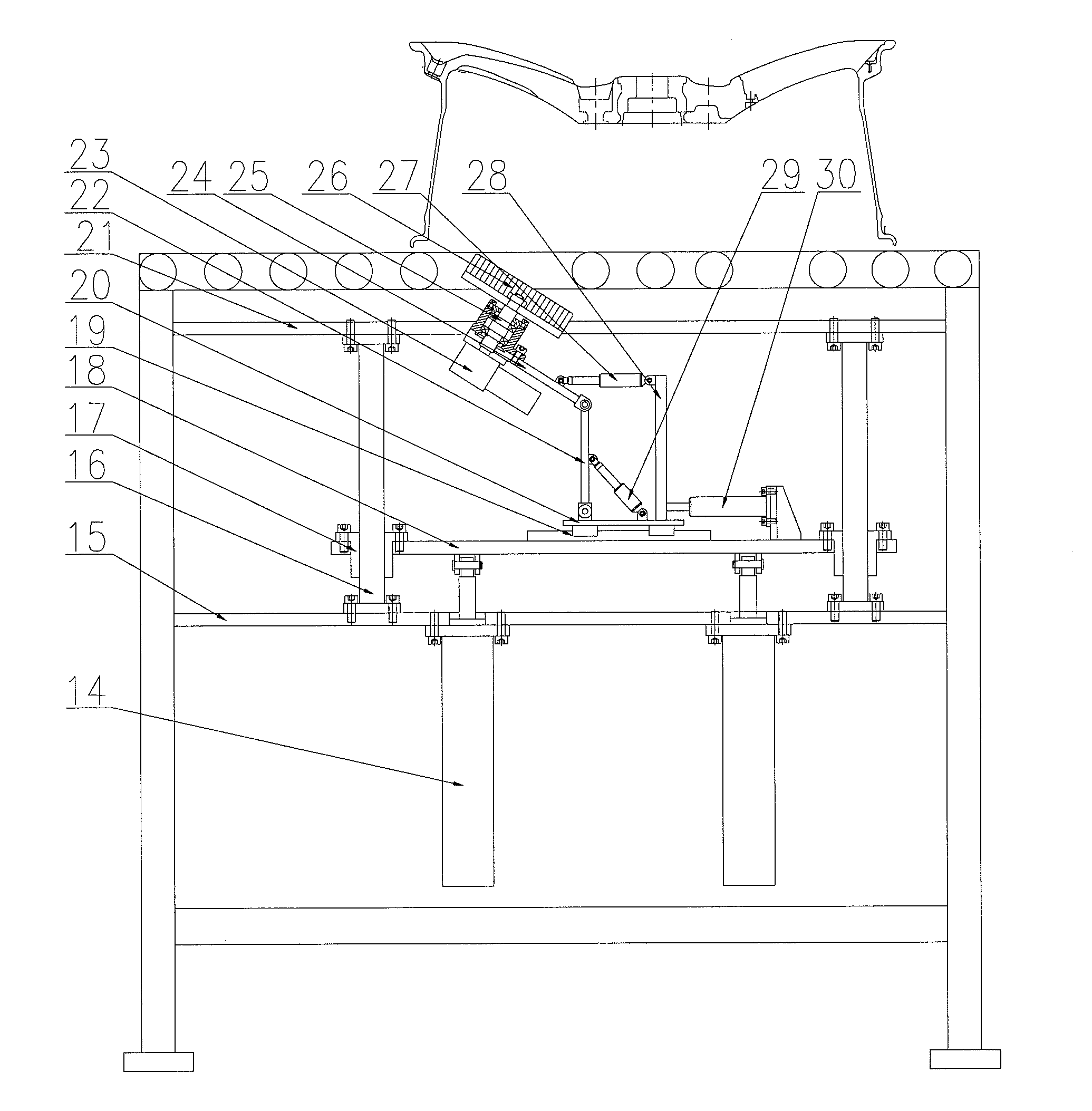
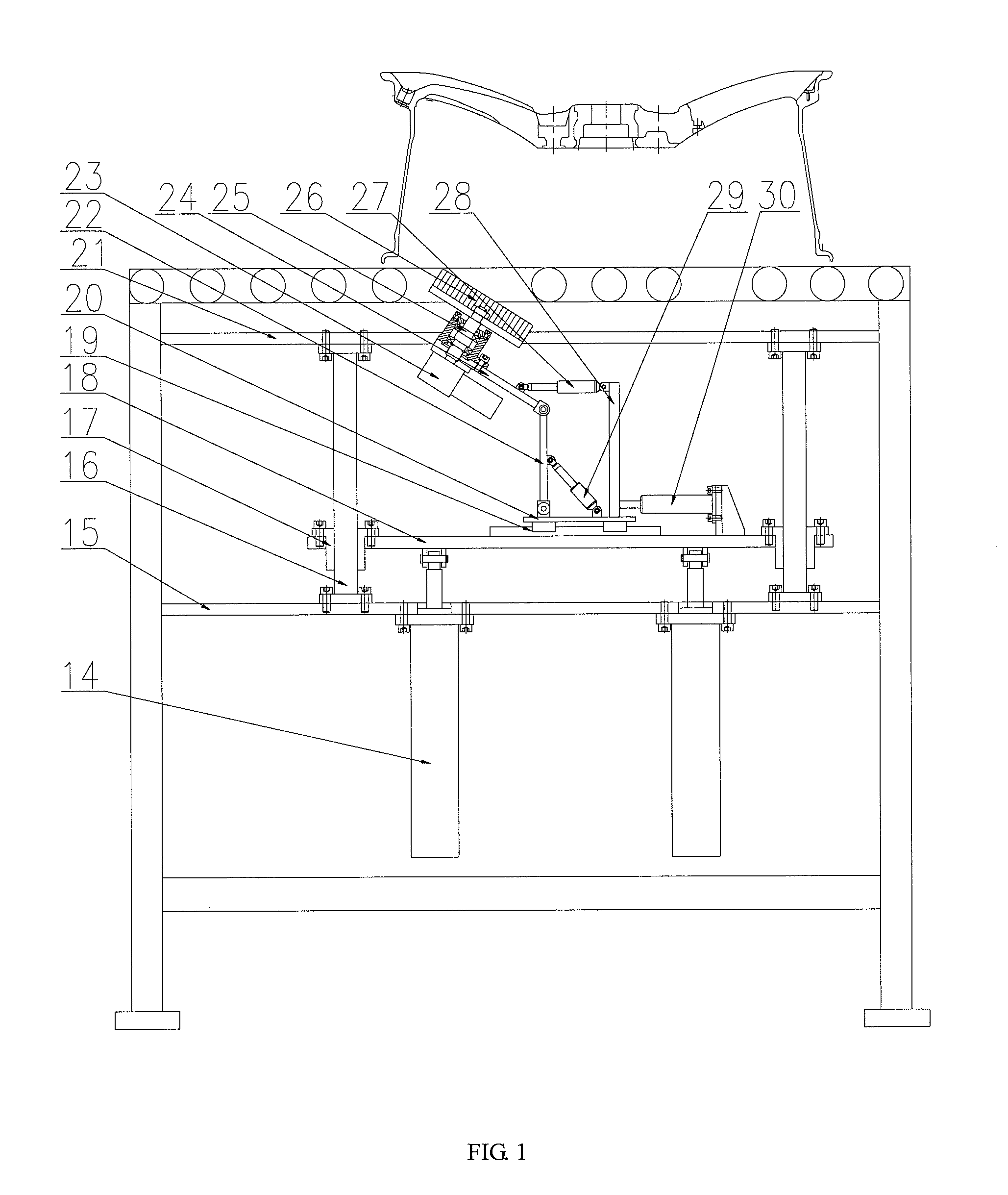
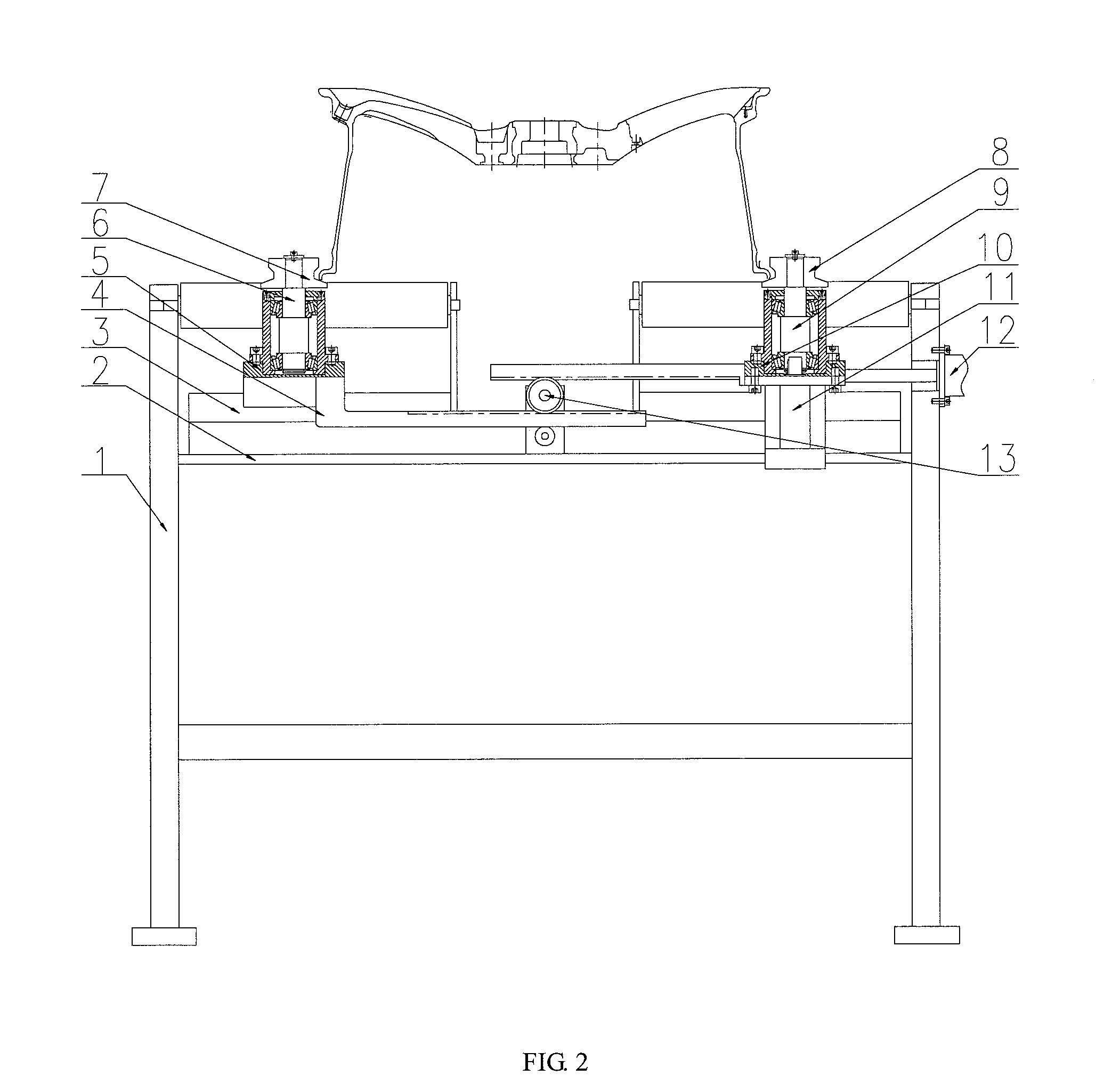
[0015]Details and working conditions of a specific device provided by the present invention will be illustrated below in combination with the accompanying drawings.

[0016]The device is composed of a frame 1, a medium plate 2, a synchronous guide rail 3, a gear rack 4, a left sliding plate 5, a left shaft 6, a left roller 7, a right roller 8, a right shaft 9, a right sliding plate 10, a servo motor 11, a clamping cylinder 12, a gear 13, a lifting cylinder 14, a lower plate 15, a guide post 16, a guide sleeve 17, a lifting plate 18, a translation guide rail 19, a translation bottom plate 20, an upper plate 21, a swing plate I 22, a motor 23, a swing plate II 24, a driving shaft 25, a hairbrush 26, a servo electric cylinder I 27, an upright post 28, a servo electric cylinder II 29 and a servo electric cylinder III 30. The synchronous guide rail 3 above which the left sliding plate 5 and the right sliding plate 10 are fixed is fixed above the medium plate 2; the gear racks 4 are fixed be...


PUM

PropertyMeasurementUnit
angleaaaaaaaaaa
shapeaaaaaaaaaa

Abstract

The present invention provides a wheel deburring device, consisting of a frame, a motor, a guide rail, a swing plate, a cylinder, a servo electric cylinder and a hairbrush and the like. When in use, the device provided by the present invention can adjust the angle of the hairbrush according to the shape of the back cavity of the wheel spoke to adapt to hubs of any style, and the deburring effect is very ideal; and meanwhile, the device has the characteristics of high degree of automation, advanced process, safe and stable performance, etc.

Description

TECHNICAL FIELD[0001]The present invention relates to the field of manufacture of aluminum alloy wheels, and particularly, to a self-adapting wheel deburring device.BACKGROUND ART[0002]In a production process of automobile aluminum alloy hubs, removal of burrs on back cavities after machining is a very important procedure, and the effect thereof directly influences subsequent coating effect. Due to the diversity of style types of hub back cavities, the traditional deburring method cannot achieve an ideal effect at all, and in order to meet the deburring demands of a variety of back cavities of wheel spokes, only the angle of a hairbrush can be adjusted to adapt to the styles thereof. However, no deburring device has this function at present.INVENTION CONTENTS[0003]The purpose of the present invention is to provide a wheel deburring device, which can adjust the angle of a hairbrush according to the shape of a back cavity of a wheel spoke to adapt to hubs of any styles.[0004]To fulfil...

Claims


Application Information

Patent Timeline
Patent Type & Authority Applications(United States)
IPC IPC(8): B24B29/00
CPCB24B29/005
Inventor XUE, BOWENGUO, JIANDONGWANG, YONGNINGZHU, ZHIHUALI, CHANGHAIXIONG, BINYU
Owner CITIC DICASTAL
Why Eureka
Try Eureka