Dragline Bucket Rigging System

a bucket and dragline technology, applied in the direction of vehicles/pulleys, mechanical equipment/dredgers, ropes and cables, etc., can solve the problems of heavy chains, heavy weight of buckets, and heavy weight of buckets, and achieve excellent tension and minimize wear.

Active Publication Date: 2016-06-30
BRIGHT TECH CO LTD
View PDF4 Cites 6 Cited by
  • Summary
  • Abstract
  • Description
  • Claims
  • Application Information

AI Technical Summary

Benefits of technology

[0025]The present invention comprises an assembly and method for using a flexible tensile member as part of the rigging for a dragline bucket. The tensile member includes a stranded core surrounded by a separate armor layer. The armor layer assumes the form of a hollow cylinder having a substantial wall thickness. The stranded core produces excellent strength in tension. The armor layer protects the stranded core from external blows and forces produced by the weight of the other parts of the bucket rigging and the hostile environment in which the bucket operates. A significant gap is provided between the outward-facing surface of the stranded core and the inward-facing surface of the armor layer. This gap minimizes wear between the two elements during the normal bending and flexing of the tensile member.

Problems solved by technology

The bucket itself often weighs many tons.
The bucket assembly is operated in a brutal environment.
Such chains are quite heavy.
The size and weight of the chains make them difficult and dangerous to handle.
In addition, the chains rapidly elongate while in use—primarily because of link-to-link abrasion.
This elongation alters the dumping geometry of the bucket assembly and reduces its performance.
In addition, the elongation of the lifting chains reduces the maximum height to which the bucket assembly may be lifted.
Another problem exists, however.
The spreader bar may weigh several tons and even the dump block assembly may exceed one ton in weight.
Further, the orientation of the “pile” of heavy components created when the bucket is laid down is random and impossible to consistently predict.
Thus, even though it is possible to use a flexible tensile member in the upper hoist assembly, a conventional flexible tensile member is not likely to survive the full range of bucket operations.
Some flexible designs have been evaluated over the years but no such design has ever been able to successfully compete with chain.

Method used


Image

  • Dragline Bucket Rigging System
  • Dragline Bucket Rigging System
  • Dragline Bucket Rigging System

Examples


Embodiment Construction

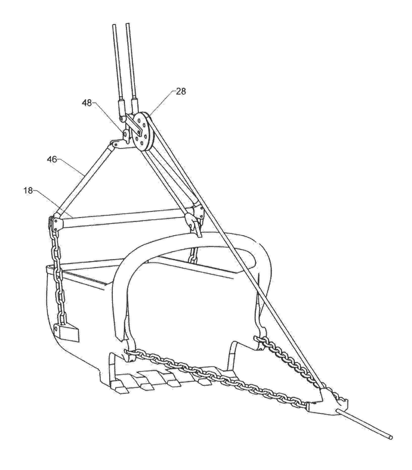
[0056]FIG. 6 shows a dragline bucket assembly made according to the present invention. A pair of bend-limited tensile members 46 are used to link each end of spreader bar 18 to yoke 48. Each tensile member replaces a prior art upper hoist chain. However, the tensile members 46 possess novel features. They are of course primarily intended to carry a tensile load, such as when the crane reels in lift ropes 14 in order to lift the bucket assembly clear of the ground.

[0057]However, as shown in FIG. 6, tension has been removed from lift ropes 14 and the dragline bucket assembly is in the process of being laid on the ground. Ordinarily the substantial weight of yoke 48 and the hardware attached to the yoke would cause the upper hoist assembly to collapse into a tangled heap. However, the construction of tensile members 46 provides a limited compressive strength in addition to their primary tensile strength.

[0058]A group of core strands carries the tensile load within each tensile member 4...


PUM


Abstract

An assembly and method for using a flexible tensile member as part of the rigging for a dragline bucket. The tensile member includes a stranded core surrounded by a separate armor layer. The armor layer assumes the form of a hollow cylinder having a substantial wall thickness. A significant gap is provided between the outward-facing surface of the stranded core and the inward-facing surface of the armor layer. This gap minimizes wear between the two elements during the normal bending and flexing of the tensile member. A first anchor is attached to a first end of the stranded core and a second anchor is attached to a second end of the stranded core. These anchors serve to transmit tension carried by the stranded core. A first end of the armor layer is also attached to the first anchor and a second end of the armor layer is attached to the second anchor.

Description

CROSS-REFERENCES TO RELATED APPLICATIONS[0001]This non-provisional patent application is a continuation-in-part of U.S. patent application Ser. No. 14 / 043,333. This application lists the same inventor as the parent application.STATEMENT REGARDING FEDERALLY SPONSORED RESEARCH OR DEVELOPMENT[0002]Not Applicable.MICROFICHE APPENDIX[0003]Not ApplicableBACKGROUND OF THE INVENTION[0004]1. Field of the Invention[0005]This invention relates to the field of mining and excavation equipment. More specifically, the invention comprises an improved rigging system for dragline buckets that reduces the need for heavy chains.[0006]2. Description of the Related Art[0007]In order to understand the significance of the present invention, it is important to have some understanding of conventional dragline bucket rigging. FIG. 1 shows dragline bucket assembly 10. As those skilled in the art will know, the dragline bucket assembly is lifted and positioned by a boom crane—typically a very large boom crane. ...

Claims


Application Information

Patent Timeline
Patent Type & Authority Applications(United States)
IPC IPC(8): E02F3/47E02F3/60E02F3/48
CPCE02F3/47E02F3/60E02F3/48E02F9/2016D07B1/18D07B2201/2074D07B2201/2089D07B2201/209D07B2201/2092D07B2201/2095D07B2401/206D07B2501/2015D07B2201/20903F16G11/042F16G13/12
Inventor CAMPBELL, RICHARD V.
Owner BRIGHT TECH CO LTD
Why Eureka
Try Eureka