Diaphragm Actuator for a Control Valve

Active Publication Date: 2016-06-30
SAMSON AG
View PDF7 Cites 0 Cited by
  • Summary
  • Abstract
  • Description
  • Claims
  • Application Information

AI Technical Summary

Benefits of technology

[0005]It is the object of the invention to provide a diaphragm actua

Problems solved by technology

Such arrangement is disadvantageous in that—if only one spring is connected in series—such spring may be prone to buckling if the valve s

Method used


Image

  • Diaphragm Actuator for a Control Valve
  • Diaphragm Actuator for a Control Valve
  • Diaphragm Actuator for a Control Valve

Examples


Embodiment Construction

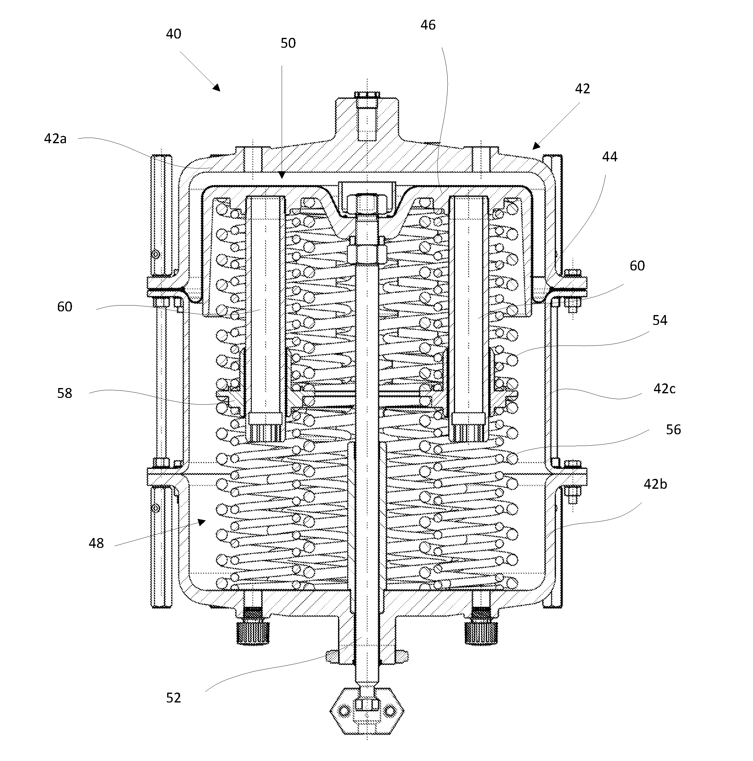
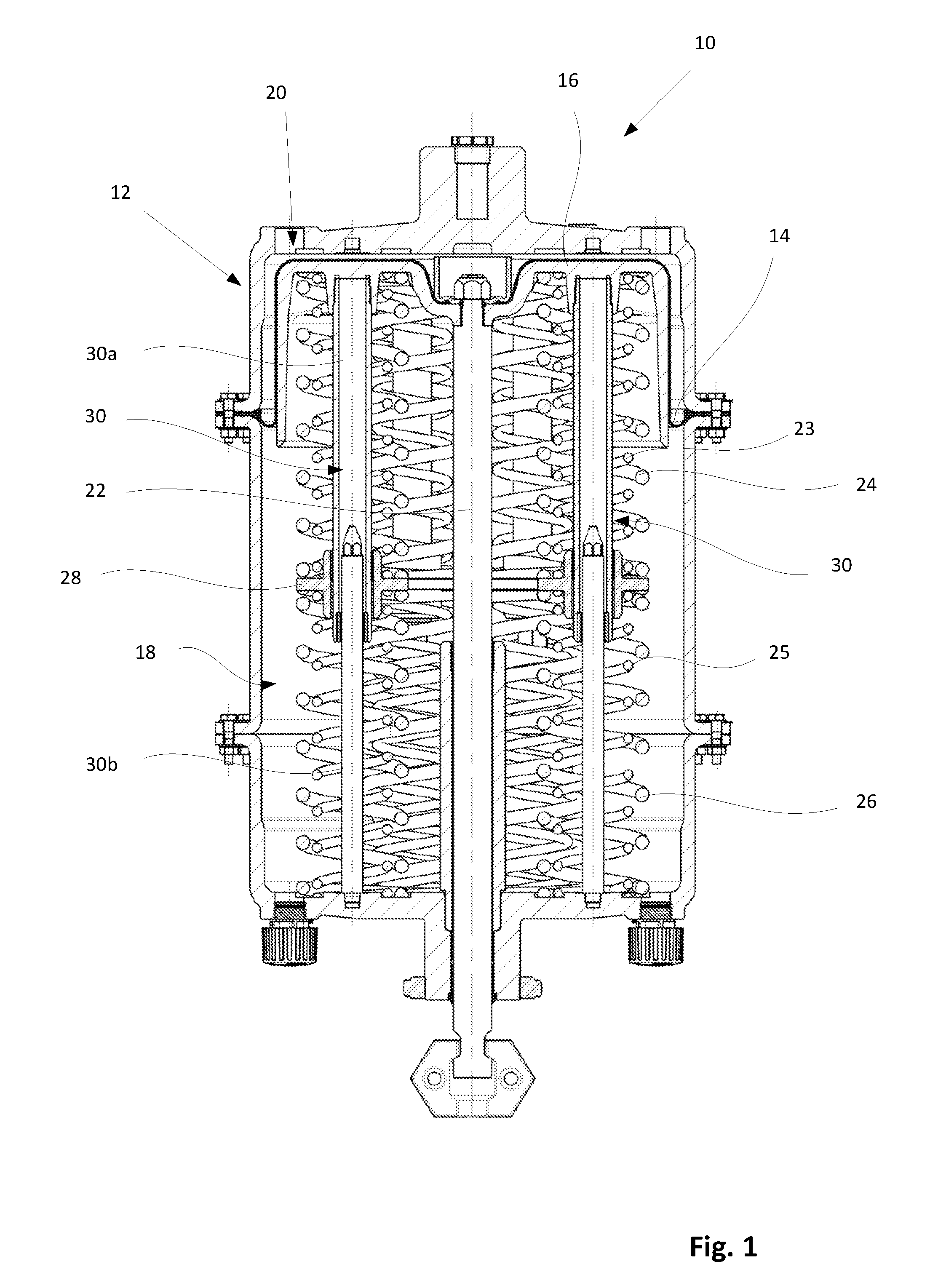
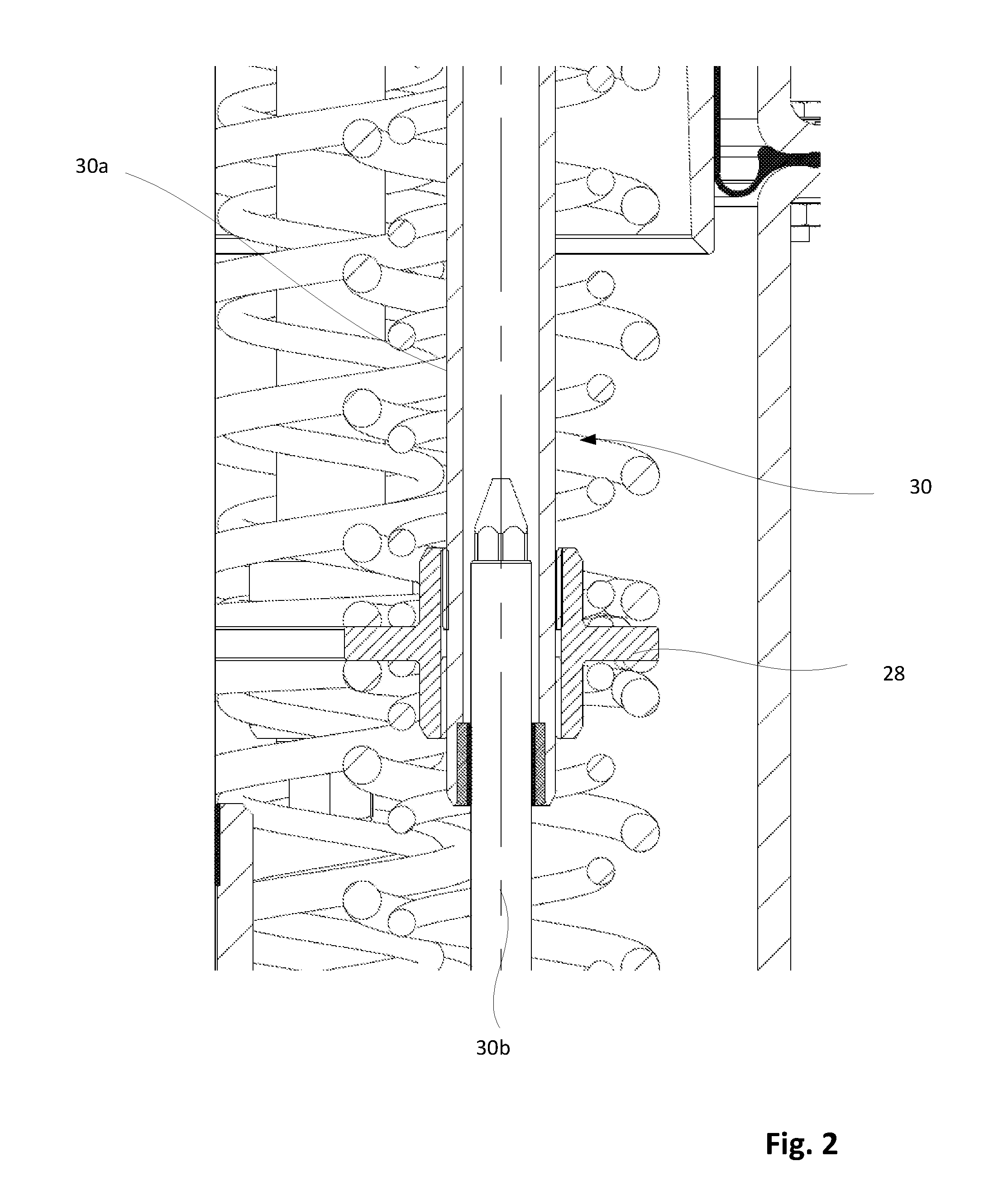
[0039]As seen in FIG. 1, the diaphragm actuator 10 of the present invention comprises an actuator housing 12 as well as a diaphragm 14 comprising a diaphragm disk 16. Diaphragm 14 acts to separate a spring chamber 18 from a pressure chamber 20. Connected to diaphragm 14 is a valve stem 22 which adjusts a valve opening by moving diaphragm 14. Springs 24, 26 are provided for setting an unpressurized initial state. Springs 24, 26 are arranged in series. Additional springs 23, 25 are connected in parallel to springs 24, 26. It is possible to connect additional springs in parallel and / or in series. Between springs 23, 24, 25, 26 a spring seat element 28 is provided which is linearly guided by telescopic rods 30. Each telescopic rod 30 comprises a first part such as a tubular element 30a and a second part such as a telescopic element 30b which is slidingly guided within said tubular element 30b (see FIG. 2). The other telescopic rods 30 are of a similar structure. Telescopic rods 30 act a...


PUM


Abstract

A diaphragm actuator (10, 40) for a control valve is shown including an actuator housing (12, 42), in which a diaphragm (14, 44) including a diaphragm disk (16, 46) is sealingly fitted thus forming a pressure chamber (20, 50), and furthermore at least one spring (24, 54) is provided which rests against the diaphragm disk (16, 46) and the actuator housing (12, 42), with the diaphragm disk (16, 46) being connected to a valve stem (22, 52) for actuating a valve body. At least two springs (26, 56) are provided and are disposed one after another in an axial direction between the actuator housing (12, 42) and the diaphragm disk (16, 46), with a spring seat element (28, 58) linearly guided by at least one linear guiding element (30, 60) being provided between the at least two springs (26, 56).

Description

BACKGROUND OF THE INVENTION[0001]The invention relates to a diaphragm actuator of a control valve as specified in the preamble of claim 1.[0002]Generic diaphragm actuators are known from U.S. Pat. No. 3,936,919, for example, and international patent WO 2008 / 112434 A1 in particular discloses a serial arrangement of springs in a diaphragm actuator. German patent document DE 10 2008 032 676 A1 discloses an expansion valve which has a gas permanently enclosed in a pressure chamber therein.[0003]European patent document EP 2 028 377 A2 relates to a diaphragm actuator for actuating a control valve. This prior art diaphragm actuator comprises an actuator housing in which a diaphragm having a diaphragm disk is sealingly fitted in the actuator housing. A pressure chamber is thus formed, wherein application of pressure to the diaphragm will cause at least one spring which is provided therein and rests against the diaphragm disk and the actuator housing to be compressed, which diaphragm actuat...

Claims


Application Information

Patent Timeline
IPC IPC(8): F16K31/126
CPCF16K31/1262F15B15/10F15B2211/30G05D16/0661
Inventor NEBEL, EUGENSIEGERT, MICHAELKOINKE, JANUSZ
Owner SAMSON AG
Why Eureka
Try Eureka