Liquid crystal display module and liquid crystal display comprising the same

a liquid crystal display module and display module technology, applied in non-linear optics, instruments, optics, etc., can solve the problems of liquid crystal displays experiencing significant deterioration in contrast ratio and brightness uniformity at the lateral sides of the display, liquid crystal displays experiencing increased deterioration in brightness uniformity with increasing

Active Publication Date: 2016-06-30
SAMSUNG SDI CO LTD
View PDF3 Cites 20 Cited by
  • Summary
  • Abstract
  • Description
  • Claims
  • Application Information

AI Technical Summary

Benefits of technology

[0007]In accordance with embodiments of the present invention, a liquid crystal display module may include a liquid crystal display module including a first polarizing plate, a second polarizing plate, and a liquid crystal panel disposed between the first polarizing plate and the second polarizing plate. The second polarizing plate includes a polarizer and an optical film formed on the polarizer. The optical film includes a high refractive index pattern layer having at least one engrav

Problems solved by technology

However, liquid crystal displays exhibit deteriorated color quality, contrast ratio and brightness uniformity at the side surfaces thereof as compared to the front surface thereof.
This causes a significant deterioration in the contrast ratio at the lateral sides of the display as compared to the contrast ratio at the front side of

Method used


Image

  • Liquid crystal display module and liquid crystal display comprising the same
  • Liquid crystal display module and liquid crystal display comprising the same
  • Liquid crystal display module and liquid crystal display comprising the same

Examples


example 1

Manufacture of Liquid Crystal Display Module

(1) Manufacture of Second Polarizing Plate

[0111]A polarizer was manufactured as in Preparative Example 3.

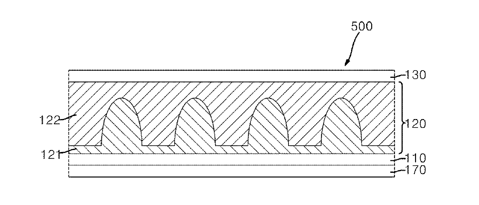
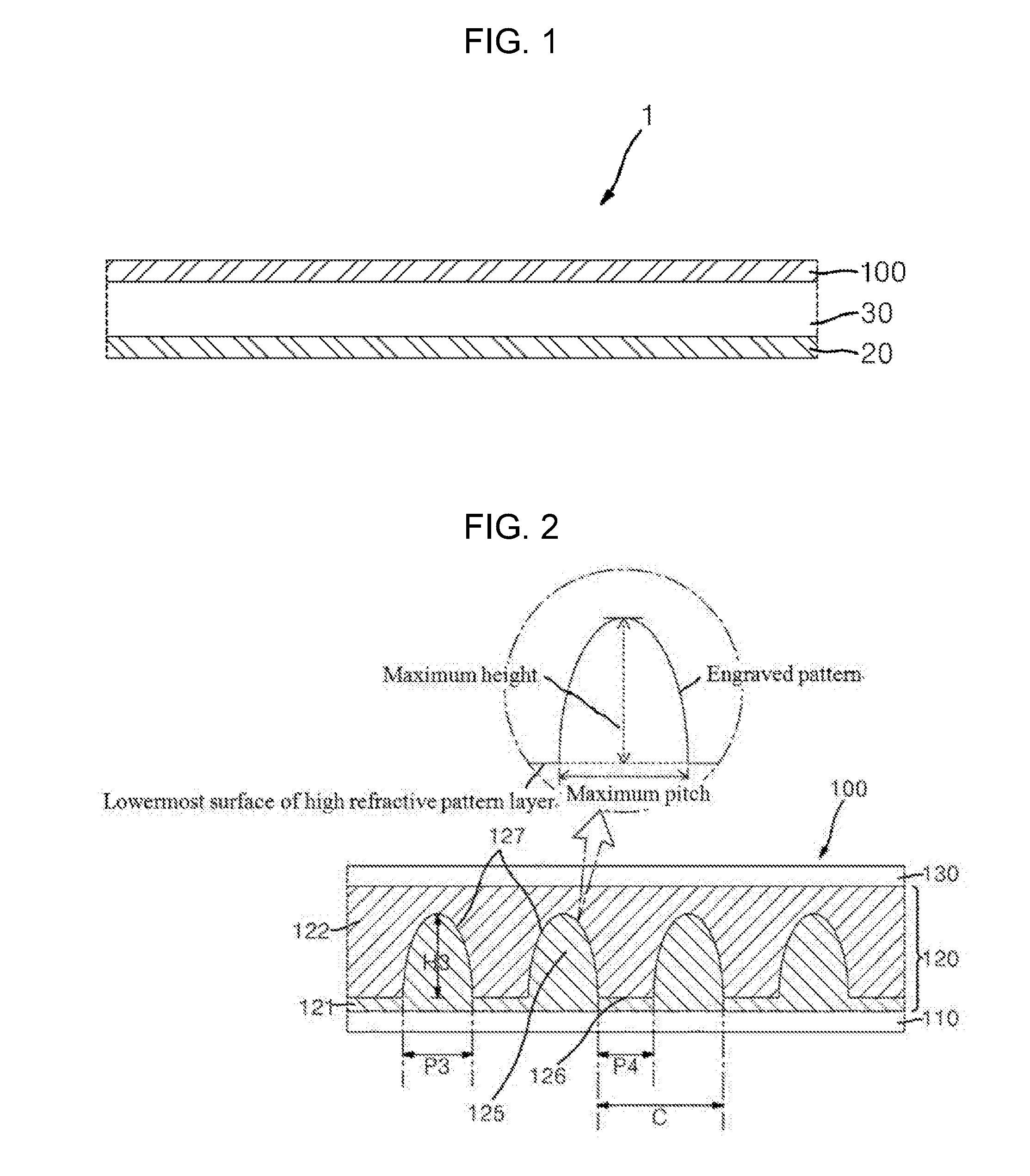
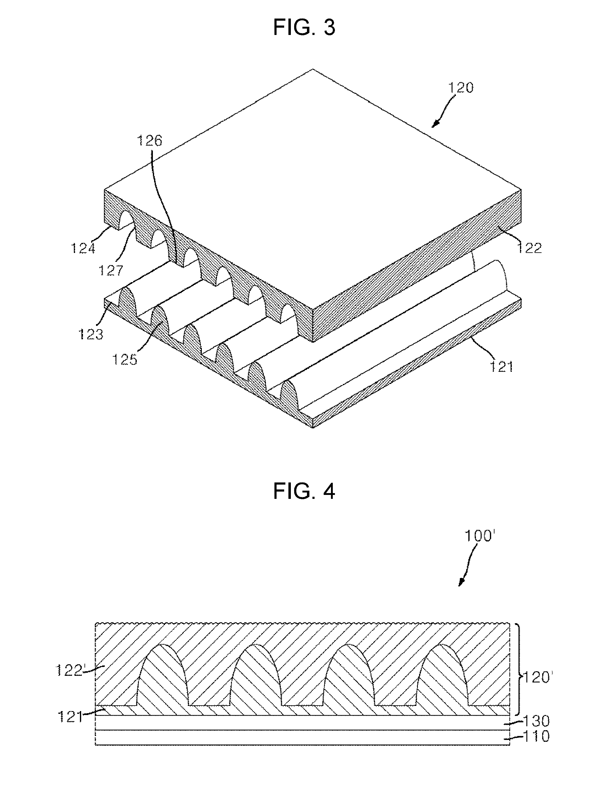
[0112]A UV-curable resin (SSC155, Shin-A T&C) was coated onto one surface of a transparent PET film as a second protective layer (SRF, thickness: 80 μm, Re=14,000 nm at a wavelength of 550 nm, Toyobo Co., Ltd.) to form a coating layer. Using a film having an embossed lenticular lens pattern (pitch: 10 μm, height: 10 μm) and a flat portion (pitch: 10 μm) alternately formed thereon, an engraved lenticular lens pattern and a flat portion were formed on the coating layer, followed by curing, thereby forming a high refractive index pattern layer. Then, a UV-curable resin (SSC140, Shin-A T&C) was coated onto the high refractive index pattern layer such that the engraved lenticular lens pattern could be completely filled with the UV-curable resin, followed by curing, thereby forming an optical film having a low refractive index pattern layer d...

example 2

Manufacture of Liquid Crystal Display Module

(1) Manufacture of Second Polarizing Plate

[0115]A polarizer was manufactured as in Preparative Example 3.

[0116]A UV-curable resin (SSC155, Shin-A T&C) was coated onto one surface of a transparent PET film as a second protective layer (SRF, thickness: 80 μm, Re=14,000 nm at a wavelength of 550 nm, Toyobo Co., Ltd.) to form a coating layer. Using a film having an embossed prism pattern (pitch: 13 μm, height: 10 μm, vertex angle: 65.5°, triangular cross-section) formed thereon, an engraved prism pattern was formed on the coating layer, followed by curing, thereby forming a high refractive index pattern layer. Then, a UV-curable resin (SSC140, Shin-A T&C) was coated onto the high refractive index pattern layer such that the engraved prism pattern could be completely filled with the UV-curable resin, followed by curing, thereby forming an optical film having a low refractive index pattern layer directly formed on the high refractive index patte...

example 3

Manufacture of Liquid Crystal Display Module

[0119]A polarizer was manufactured as in Preparative Example 3.

[0120]A UV-curable resin (SSC155, Shin-A T&C) was coated onto one surface of a transparent PET film as a second protective layer (SRF, thickness: 80 μm, Re=14,000 nm at a wavelength of 550 nm, Toyobo Co., Ltd.) to form a coating layer. Using a film having an embossed lenticular lens pattern (pitch: 10 μm, height: 10 μm) and a flat portion (pitch: 10 μm) alternately formed thereon, an engraved lenticular lens pattern and a flat portion were formed on the coating layer, followed by curing, thereby forming a high refractive index pattern layer. Then, a UV-curable resin (SSC143, Shin-A T&C) was coated onto the high refractive index pattern layer such that the engraved lenticular lens pattern could be completely filled with the UV-curable resin, followed by curing, thereby forming an optical film having a low refractive index pattern layer directly formed on the high refractive inde...


PUM


Abstract

A liquid crystal display module includes first and second polarizing plates, and a liquid crystal panel between the polarizing plates. The second polarizing plate comprises an optical film on a polarizer. The optical film comprises a high refractive index pattern layer having at least one engraved pattern, and a low refractive index pattern layer having a filling pattern that fills at least a portion of the engraved pattern. A difference in refractive index between the high refractive index pattern layer and the low refractive index pattern layer may be about 0.1 to about 0.2. The optical film may be disposed such that light emitted from the liquid crystal panel will enter the low refractive index pattern layer and then be emitted through the high refractive index pattern layer.

Description

CROSS-REFERENCE TO RELATED APPLICATIONS[0001]This application claims priority to and the benefit of Korean Patent Application Nos. 10-2014-0196078 filed Dec. 31, 2014, 10-2014-0196079 filed Dec. 31, 2014, and 10-2015-0154142 filed Nov. 3, 2015, all filed in the Korean Intellectual Property Office, the entire contents of both of which are incorporated herein by reference.BACKGROUND[0002]1. Technical Field[0003]Embodiments of the present invention relate to a liquid crystal display module and a liquid crystal display including the same.[0004]2. Description of the Related Art[0005]Liquid crystal displays emit light through a liquid crystal panel after receiving the light from a backlight unit. Thus, liquid crystal displays may provide good color quality at a front side thereof. However, liquid crystal displays exhibit deteriorated color quality, contrast ratio and brightness uniformity at the side surfaces thereof as compared to the front surface thereof. Various attempts have been mad...

Claims


Application Information

Patent Timeline
IPC IPC(8): G02F1/13363G02F1/1337G02F1/1335
CPCG02F1/13363G02F1/133528G02F2001/133742G02F1/133504G02F1/1337G02F1/133502G02F1/133606G02F1/133611G02F1/133607G02F1/133507
Inventor JU, YOUNG HYUNKIM, YOUNG MINOH, YOUNG
Owner SAMSUNG SDI CO LTD
Why Eureka
Try Eureka