
Systems and methods of determining a type and feature set of a light source, and the control thereof

a technology of light source and feature set, which is applied in the direction of lighting and heating equipment, process and machine control, instruments, etc., can solve the problems of not providing dimming or not providing smart light source control, and not providing traditional light source control

Active Publication Date: 2016-06-30
GOOGLE LLC
View PDF6 Cites 73 Cited by
  • Summary
  • Abstract
  • Description
  • Claims
  • Application Information

AI Technical Summary

Benefits of technology

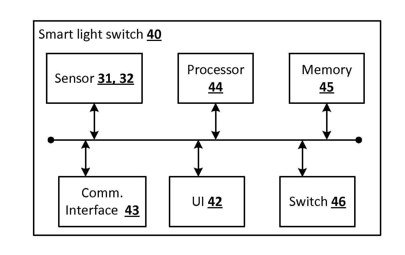
The patent describes a smart light switch that can detect the type of light source connected to it, such as LED, CFL, or incandescent. The switch can then set a series of operations based on the type of light source, and control the light source to perform those operations. The technical effect of this innovation is that it allows for more efficient and effective control of light sources, improving the overall performance and efficiency of the system.

Problems solved by technology

The first category of currently-available switches provide remote electrical switching capabilities, but do not provide dimming or smart light source control.
A second category of currently-available switches provides remote electrical switching capabilities with dimming, but does not provide smart light source control.
A third category of currently-available switches provides smart light source control, but does not provide control of traditional light sources.
Although traditional dimmer switches can used with compact fluorescent lights (CFLs), they can cause flickering and shortened lifespan due to multiple re-strikes.
Moreover, current smart light sources can only be controlled via software controls.
That is, if a user attempts to control a smart light source with a traditional dimmer switch, the dimmer switch will not be able to control a dimming operation or any other operation of the smart light source.

Method used


Image

  • Systems and methods of determining a type and feature set of a light source, and the control thereof
  • Systems and methods of determining a type and feature set of a light source, and the control thereof
  • Systems and methods of determining a type and feature set of a light source, and the control thereof

Examples


Embodiment Construction

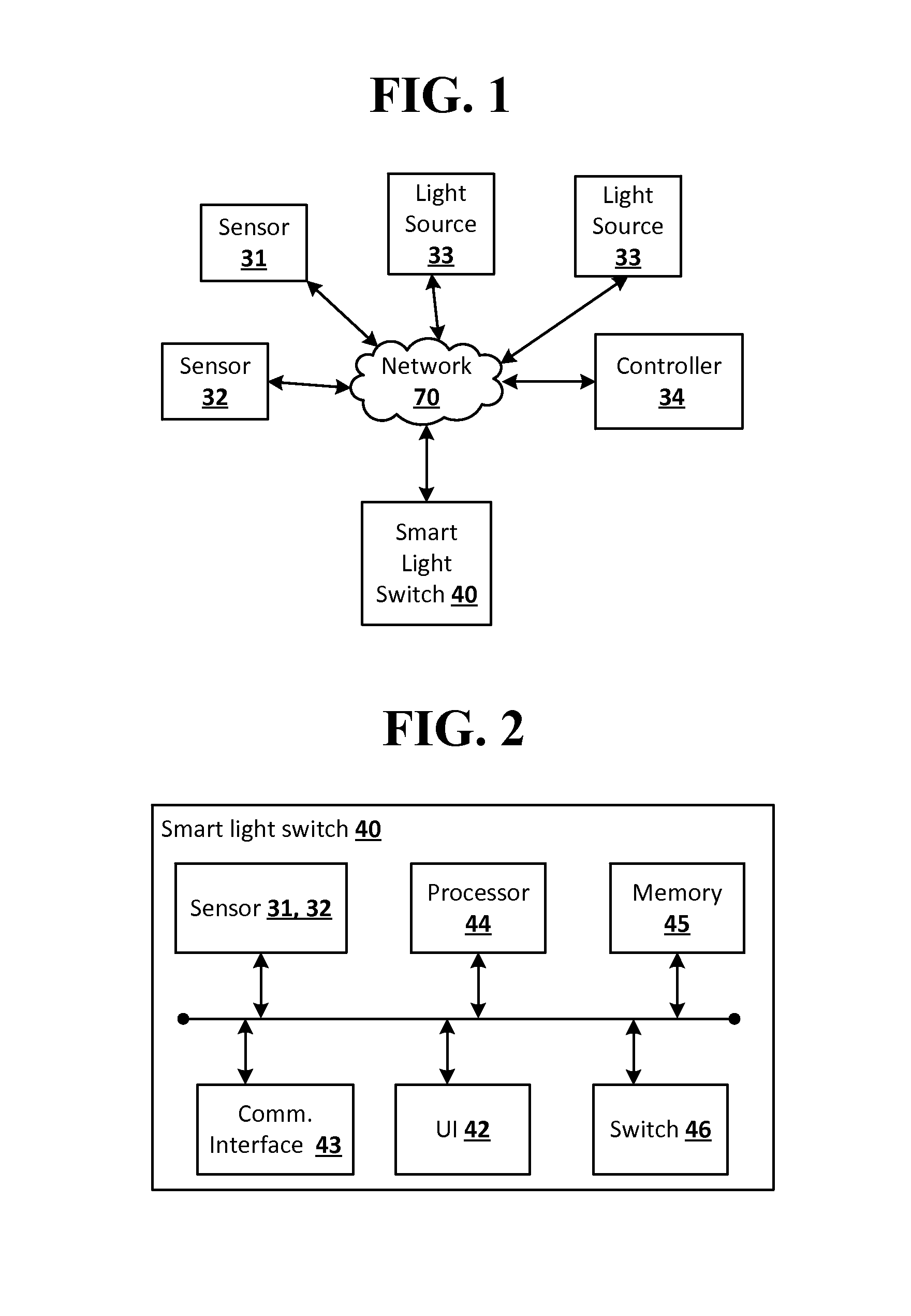
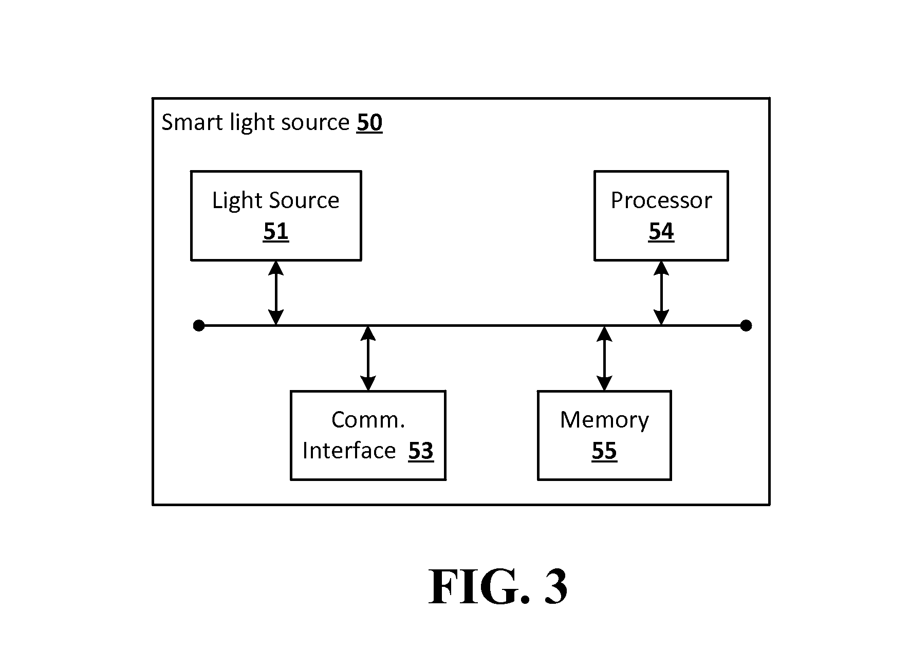
[0018]Embodiments of the disclosed subject matter provide systems and methods to determine a type of a light source coupled to a smart light switch, where the smart light switch can change modes and features to match the capabilities of the determined type of light source. The embodiments of the disclosed subject matter provide a smart light switch to work with a wide variety of light sources, thus minimizing the difficulty of a user to properly select a light source that is compatible with a switch, and maximizing the features accessible by the user for switch and light source combinations. The embodiments of the disclosed subject matter provide increased ease of use of the remote control of light sources.

[0019]FIG. 1 shows an example of a light switch (e.g., a smart light switch 40) and light source network as disclosed herein, which may be implemented over any suitable wired and / or wireless communication networks 70, and / or electrical power networks.

[0020]One or more sensors 31, ...


PUM


Abstract

Systems and methods of the disclosed subject matter provide to detect the signature of a light source through either electrical signature on a circuit or external light signatures output by the light source, and a switch can change modes and features to match the capabilities of the connected light source. Embodiments of the disclosed subject matter provide a light source, a sensor to determine a type of the light source, and a switch, including a processor, to determine a set of operations according to the determined type of light source, and to control the light source to perform a selected operation from the determined set of operations.

Description

BACKGROUND[0001]Currently-available “smart switches” to control lighting fall into several categories. The first category of currently-available switches provide remote electrical switching capabilities, but do not provide dimming or smart light source control. A second category of currently-available switches provides remote electrical switching capabilities with dimming, but does not provide smart light source control. A third category of currently-available switches provides smart light source control, but does not provide control of traditional light sources.[0002]Although traditional dimmer switches can used with compact fluorescent lights (CFLs), they can cause flickering and shortened lifespan due to multiple re-strikes. Dimmer switches that are compatible with CLFs and LED (light emitting diode) light sources typically have dimmers with complex matrixes that govern which light sources (i.e., bulbs) can be used.[0003]In present lighting systems, smart light sources can be mad...

Claims


Application Information

Patent Timeline
Patent Type & Authority Applications(United States)
IPC IPC(8): H05B37/02H05B39/04H05B33/08F21V23/04H05B41/39H05B44/00
CPCH05B37/0209F21V23/045H05B39/041H05B33/0848H05B41/39H05B47/175H05B47/105H05B47/11Y02B20/40H05B45/14
Inventor KEITH, DAVID WILLIAM
Owner GOOGLE LLC
Learn More