
Electronic component mounting machine and transfer confirmation method

a technology of electronic components and mounting machines, which is applied in the field of electronic components, can solve the problems of difficult to distinguish the electrodes from the viscous fluid in the grayscaling method, and the transfer confirmation of the viscous fluid may not be appropriately performed, and achieves high resolution, high precision, and high resolution

Inactive Publication Date: 2016-06-30
FUJI MASCH MFG CO LTD
View PDF8 Cites 1 Cited by
  • Summary
  • Abstract
  • Description
  • Claims
  • Application Information

AI Technical Summary

Benefits of technology

The patent relates to an electronic component mounting machine that uses a viscous fluid to transfer components to a circuit board. The machine detects the height of the electrodes before and after the fluid is applied, ensuring accurate transfer of the fluid to the electrodes. This is achieved through the use of a line sensor that uses high-frequency laser light to detect the height of the electrodes, providing precise confirmation of the transfer. Additionally, the machine can also use the sensor that checks the coplanarity of the electrodes to confirm the transfer of the viscous fluid. This eliminates the need for a separate sensor for confirming the transfer of the solder, reducing costs.

Problems solved by technology

In other words, even though the viscous fluid is transferred to the electrodes, the diameter of the electrodes after the transferring of the viscous fluid and the diameter of the electrodes before the transferring of the viscous fluid are approximately the same based on the imaging data, and the transfer confirmation of the viscous fluid to the electrodes may not be appropriately performed.
However, since many of the viscous fluids have high transparency, it is difficult to distinguish the electrodes from the viscous fluid in the grayscaling method.

Method used


Image

  • Electronic component mounting machine and transfer confirmation method
  • Electronic component mounting machine and transfer confirmation method
  • Electronic component mounting machine and transfer confirmation method

Examples


Embodiment Construction

[0019]Hereinafter, detailed description will be given of the example of the present disclosure with reference to the drawings as a mode for carrying out the present disclosure.

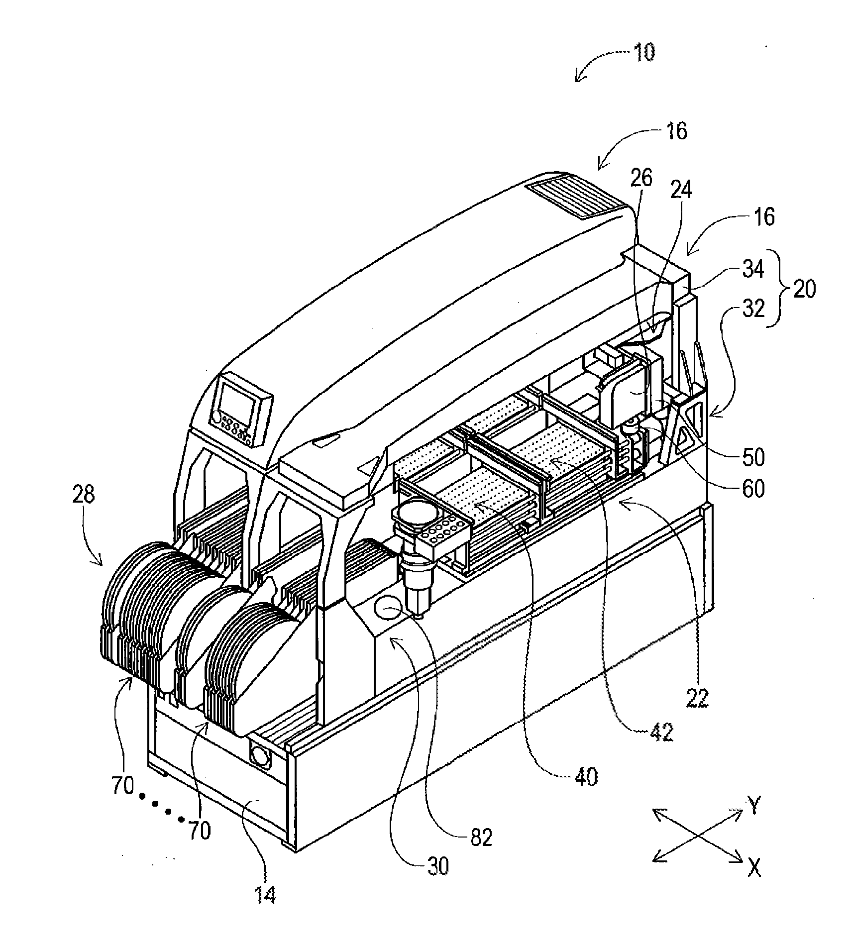
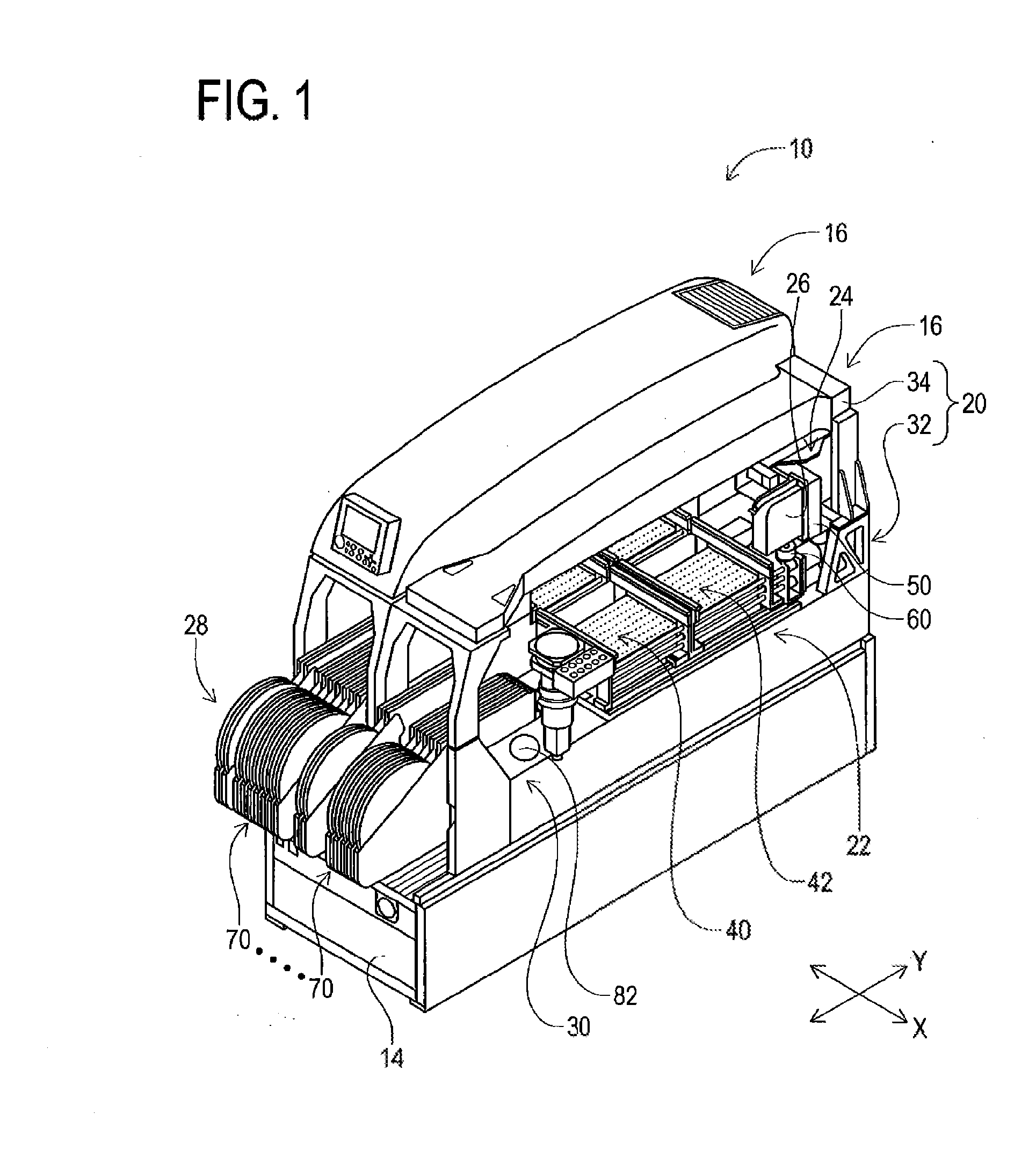
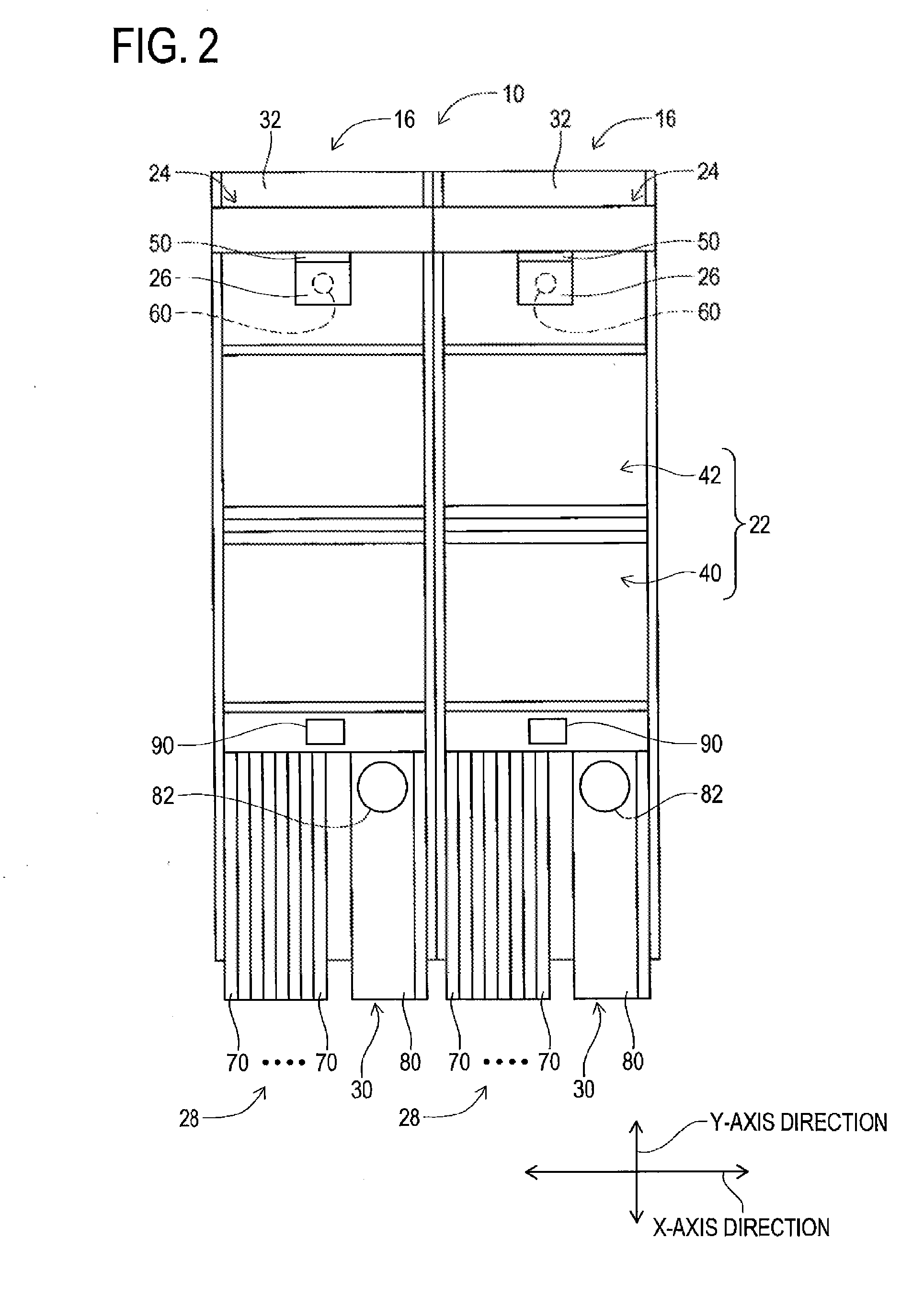
[0020]FIG. 1 and FIG. 2 illustrate an electronic component mounting device 10. FIG. 1 is a perspective view of the electronic component mounting device 10, and FIG. 2 is a plan view illustrating the electronic component mounting device 10 as viewed from above in a state in which a cover or the like is removed. The electronic component mounting device 10 is a device for mounting an electronic component on a circuit board. The electronic component mounting device 10 includes one system base 14, and two mounting machines 16 which are installed on the system base 14 to line up. Note that, in the following description, a direction in which the mounting machines 16 are lined up will be referred to as an X-axis direction, and a horizontal direction at a right angle to the X-axis direction will be referred to as a Y-a...


PUM


Abstract

In an electronic component mounting machine which mounts electronic components, to an electrode of which a viscous fluid is transferred, on a circuit board, a height of the electrode before transferring the viscous fluid (dotted line) and the height of the electrode after transferring the viscous fluid (solid line) are detected by a height sensor. The transferring of the viscous fluid to the electrode is confirmed by comparing the height of the electrode before the transferring of the viscous fluid and the height of the electrode after the transferring of the viscous fluid. If the difference between the height of the electrode before the transferring of the viscous fluid and the height of the electrode after the transferring of the viscous fluid is greater than or equal to a predetermined value, it is determined that the transferring of the viscous fluid to the electrode is appropriately performed.

Description

TECHNICAL FIELD[0001]The present disclosure relates to an electronic component mounting machine which mounts an electronic component, to the electrodes of which a viscous fluid is transferred, on a circuit board, and relates to a transfer confirmation method which confirms the transfer state of the viscous fluid onto the electrodes of the electronic component.BACKGROUND ART[0002]There is an electronic component mounting machine which is provided with a mounting head which holds an electronic component and a viscous fluid tray which stores a viscous fluid, in which the viscous fluid is transferred to the electrodes of the electronic component which is held by the mounting head, and the electronic component is mounted on the circuit board. In such an electronic component mounting machine, when the transferring of the viscous fluid to the electrodes is not appropriately performed, the electronic component may not be appropriately mounted on the circuit board. Therefore, in the electron...

Claims


Application Information

Patent Timeline
Patent Type & Authority Applications(United States)
IPC IPC(8): H05K13/08G01B11/00H05K13/04
CPCH05K13/08G01B11/00H05K13/0404H05K13/0465H05K13/0812
Inventor YAMADA, KAZUNORI
Owner FUJI MASCH MFG CO LTD
Learn More