Image forming apparatus and transfer belt used therein

a technology of image forming apparatus and transfer belt, which is applied in the direction of thin material processing, article separation, printing, etc., can solve the problems of drier ink having an increased viscosity, prone to deflection or distortion in itself, and recording medium may also be deflected or positionally displaced, so as to simplify maintenance operation and cost reduction

Inactive Publication Date: 2008-01-03
BROTHER KOGYO KK
View PDF14 Cites 0 Cited by
  • Summary
  • Abstract
  • Description
  • Claims
  • Application Information

AI Technical Summary

Benefits of technology

[0043] The outer belt designed to be detachably attached to the inner belts may be repl

Problems solved by technology

In the case of a large image forming area, the transfer belt is required to be long and, therefore, is prone to have deflection or distortion in itself.
As a result, the recording medium may also be deflected or positionally displaced by the influence of the deflection or distortion of the belt.
In the vicinity of ink discharge ports of the print head, volatile components such as water in ink evaporate with time, which leads to a drier ink having an increased viscosity.
In an on-demand ink jet printer, in which whether or not to discharge ink is determined based on the data to be recorded, especially an ink discharge port with a low frequency of ink discharge w

Method used


Image

  • Image forming apparatus and transfer belt used therein
  • Image forming apparatus and transfer belt used therein
  • Image forming apparatus and transfer belt used therein

Examples


Embodiment Construction

[0065] Hereinafter, an embodiment of the present invention will be described with reference to the drawings.

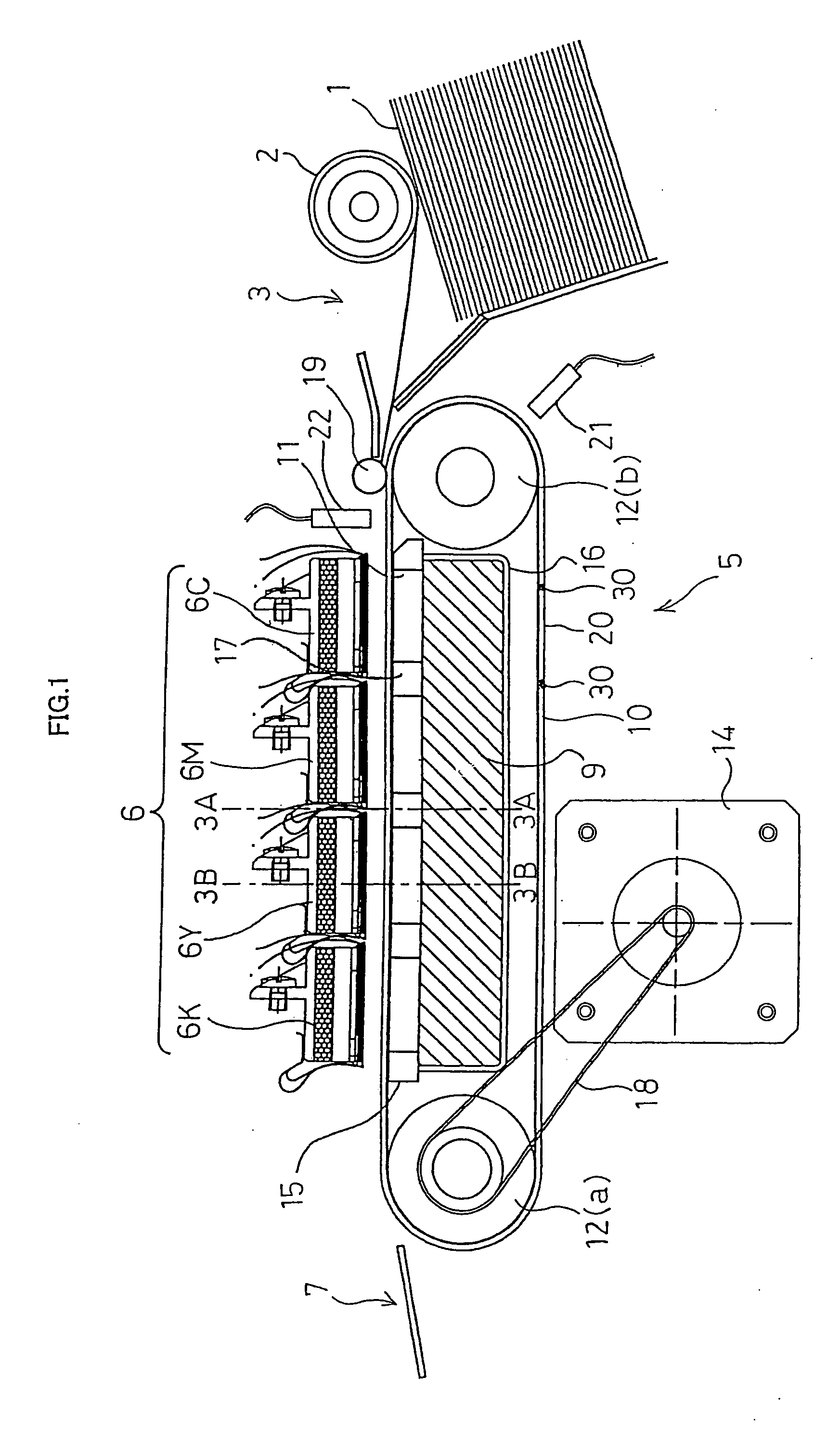
[0066]FIG. 1 is a schematic view illustrating the main part of an ink jet printer according to the embodiment of the present invention. The ink jet printer according to the present embodiment has the same basic structure as a general ink jet printer. As shown in FIG. 1, the ink jet printer comprises a supply portion 3 including a pickup roller 2 for feeding paper 1 as a recording medium, a transfer mechanism 5 for transferring the paper 1 supplied from the supply portion 3, a print head 6 of ink jet system, and a discharge portion 7 for discharging the paper 1.

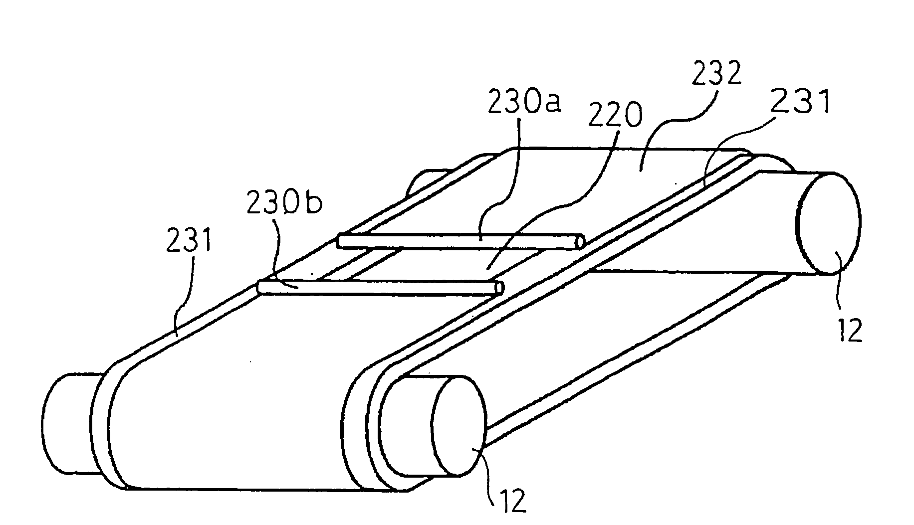
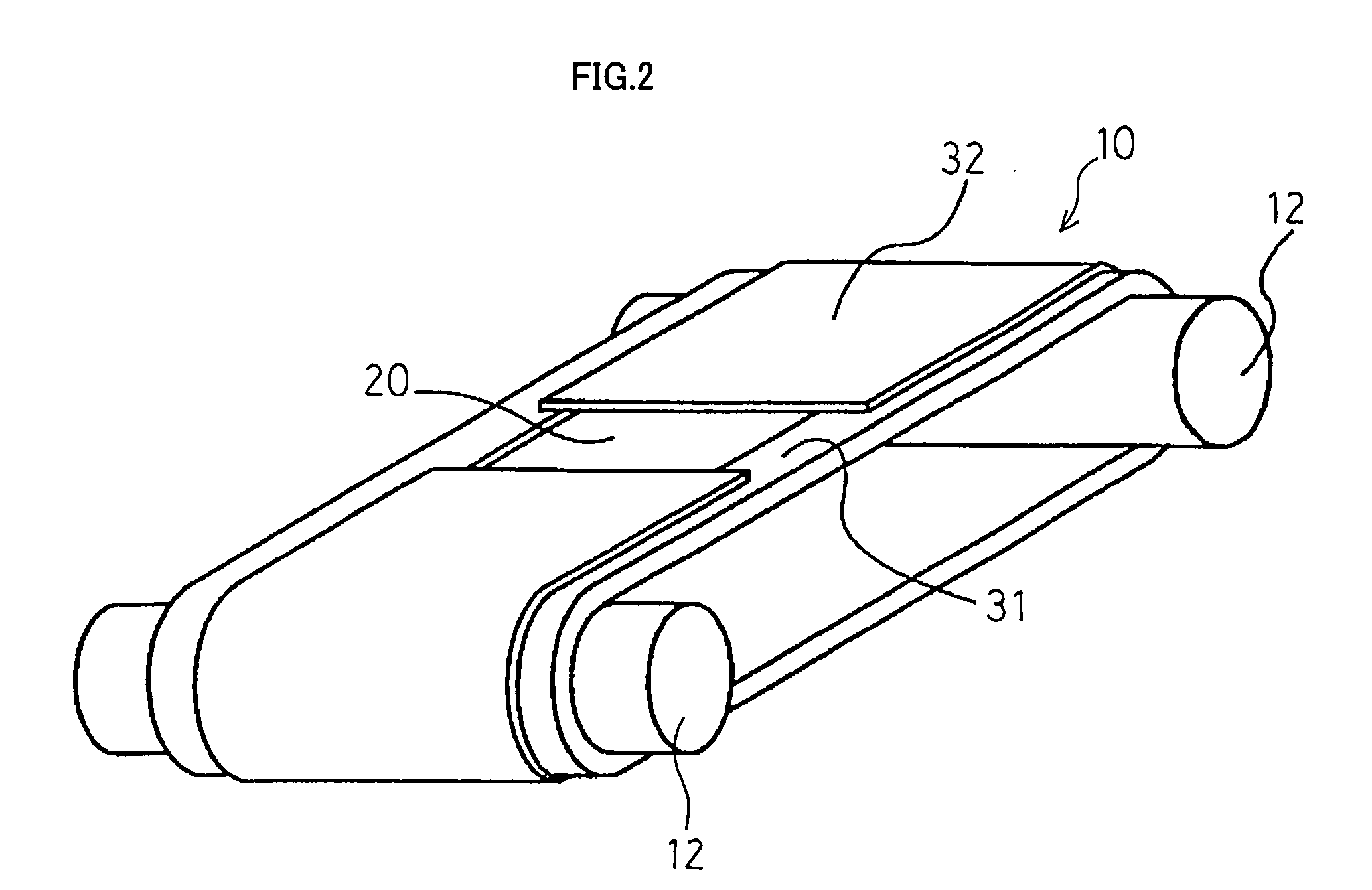
[0067] The transfer mechanism 5 is provided with two transfer rollers 12, 12, a transfer belt 10 wound around the transfer rollers 12, 12, and a transfer motor 14 for driving one of the transfer rollers 12, 12 as a drive roller.

[0068] In the ink jet printer, the paper 1 is fed from the supply portion 3 toward the tran...


PUM


Abstract

A transfer belt (10) has a two-layer structure consisting of two inner belts (31) formed of metal, such as stainless steel, and an outer belt (32) formed of an elastic material, such as silicone rubber, being spread across the inner belts (31). The inner belts (31) are endless and wound around transfer rollers (12), while the outer belt (32) has its ends which are not joined with each other and form an opening (20) therebetween. Distortion of the outer belt (32) due to stress is designed to be suppressed by using a reinforcing member around the opening (20).

Description

[0001] This is a Continuation of application Ser. No. 10 / 490,430 filed Mar. 24, 2004, which is a PCT National Stage Application of PCT / JP03 / 02761, filed Mar. 7, 2003. The entire disclosures of the prior applications are hereby incorporated by reference herein in their entireties.FIELD OF THE INVENTION [0002] The present invention relates to an image forming apparatus, such as an ink jet printer, and a transfer belt used in the image forming apparatus. BACKGROUND ART [0003] Image forming apparatuses, which record images and the like on recording media, such as paper and cloth, while transferring these recording media, have been conventionally used extensively. In some image forming apparatuses, transfer of a recording medium using a transfer belt (belt transfer system) is employed since the recording medium can be transferred in a rapid and stable manner by this system. [0004] In the belt transfer system, an endless transfer belt is wound around a plurality of transfer rollers, and t...

Claims


Application Information

Patent Timeline
IPC IPC(8): B41J2/01B41J11/00B65H5/02
CPCB41J11/007B65H2404/243B65H5/025
Inventor NAKASHIMA, ATSUHISA
Owner BROTHER KOGYO KK
Why Eureka
Try Eureka