Elevator control apparatus

a control apparatus and elevator technology, applied in elevators, hoisting equipment, transportation and packaging, etc., can solve the problem that the brake cannot perform a braking operation, and achieve the effect of reducing size, preventing the production of unwanted noise, and controlling more reliably

Active Publication Date: 2016-07-07
MITSUBISHI ELECTRIC CORP
View PDF12 Cites 4 Cited by
  • Summary
  • Abstract
  • Description
  • Claims
  • Application Information

AI Technical Summary

Benefits of technology

[0008]According to the elevator control apparatus of the one embodiment of the present invention, the operation of the brake may be controlled more reliably, the production of unwanted noise may be prevented, and the size reduction may be achieved.

Problems solved by technology

When there is only one electromagnetic switch, in a case where an ON failure of the electromagnetic switch occurs, the brake cannot perform a braking operation.

Method used


Image

  • Elevator control apparatus
  • Elevator control apparatus
  • Elevator control apparatus

Examples


first embodiment

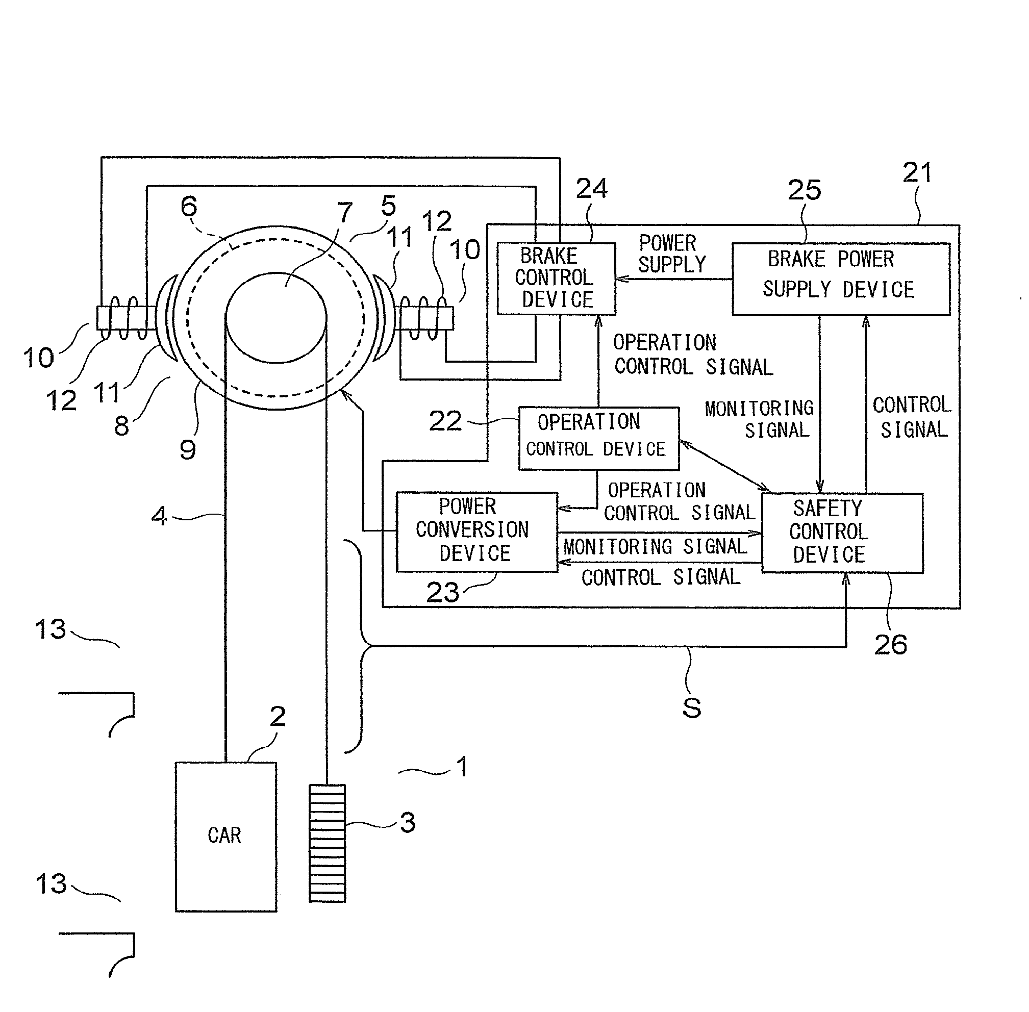
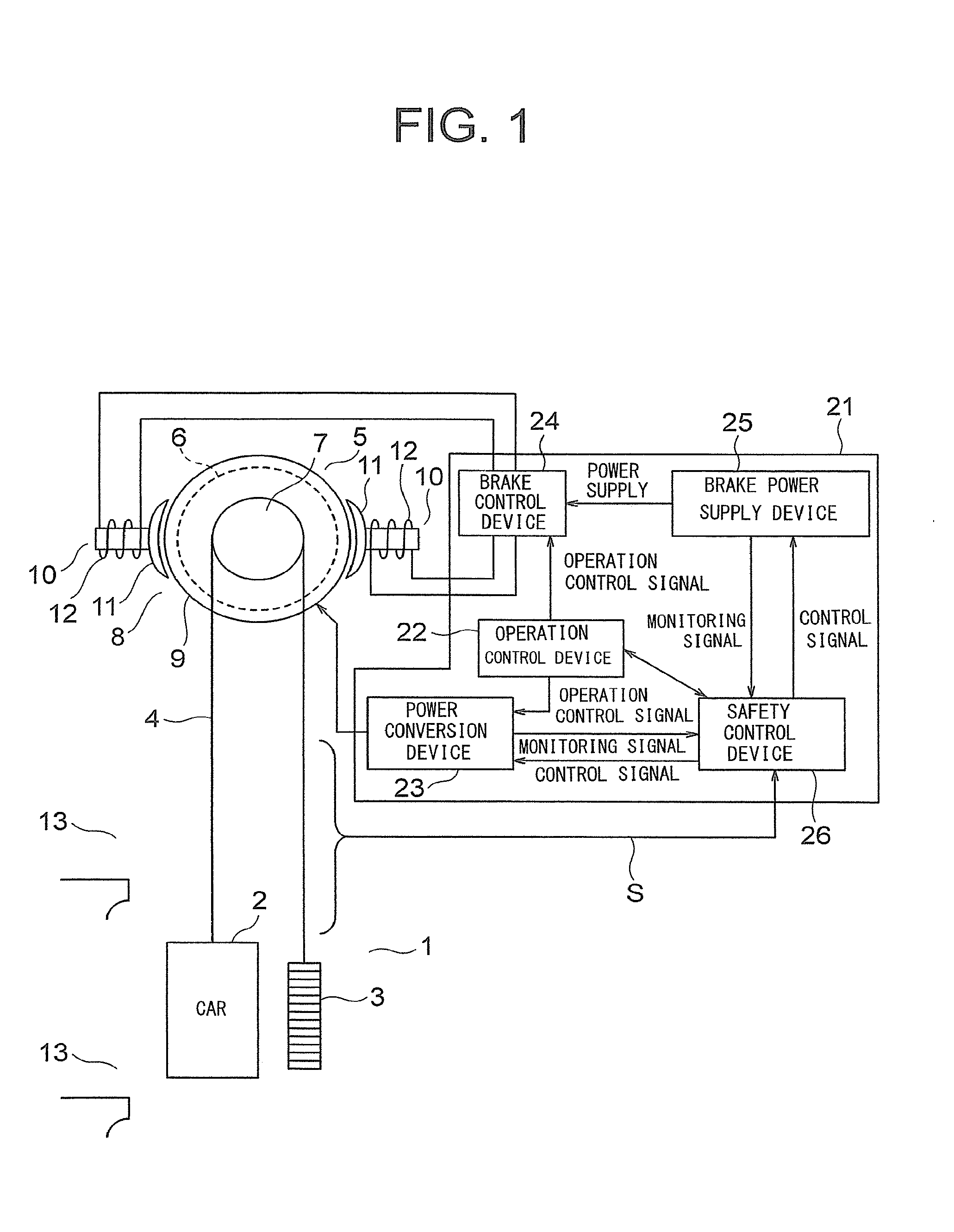
[0016]FIG. 1 is a configuration diagram for illustrating an elevator according to a first embodiment of the present invention. In FIG. 1, a car 2 and a counterweight 3 are suspended by a main cable 4 in a hoistway 1. As the main cable 4, for example, a rope, a belt, or the like is used. At an upper portion of the hoistway 1, a hoisting machine 5 for producing a driving force for moving the car 2 and the counterweight 3 is arranged.

[0017]The hoisting machine 5 includes a hoisting machine main body 6 including a motor, a drive sheave 7 rotatably arranged on the hoisting machine main body 6, and a brake 8 for applying a braking force on the drive sheave 7.

[0018]The main cable 4 is wound around the drive sheave 7. The drive sheave 7 is rotated by a driving force of the motor in the hoisting machine main body 6. The car 2 and the counterweight 3 are moved in up and down directions in the hoistway 1 by the rotation of the drive sheave 7.

[0019]The brake 8 includes a rotating body 9 configu...

second embodiment

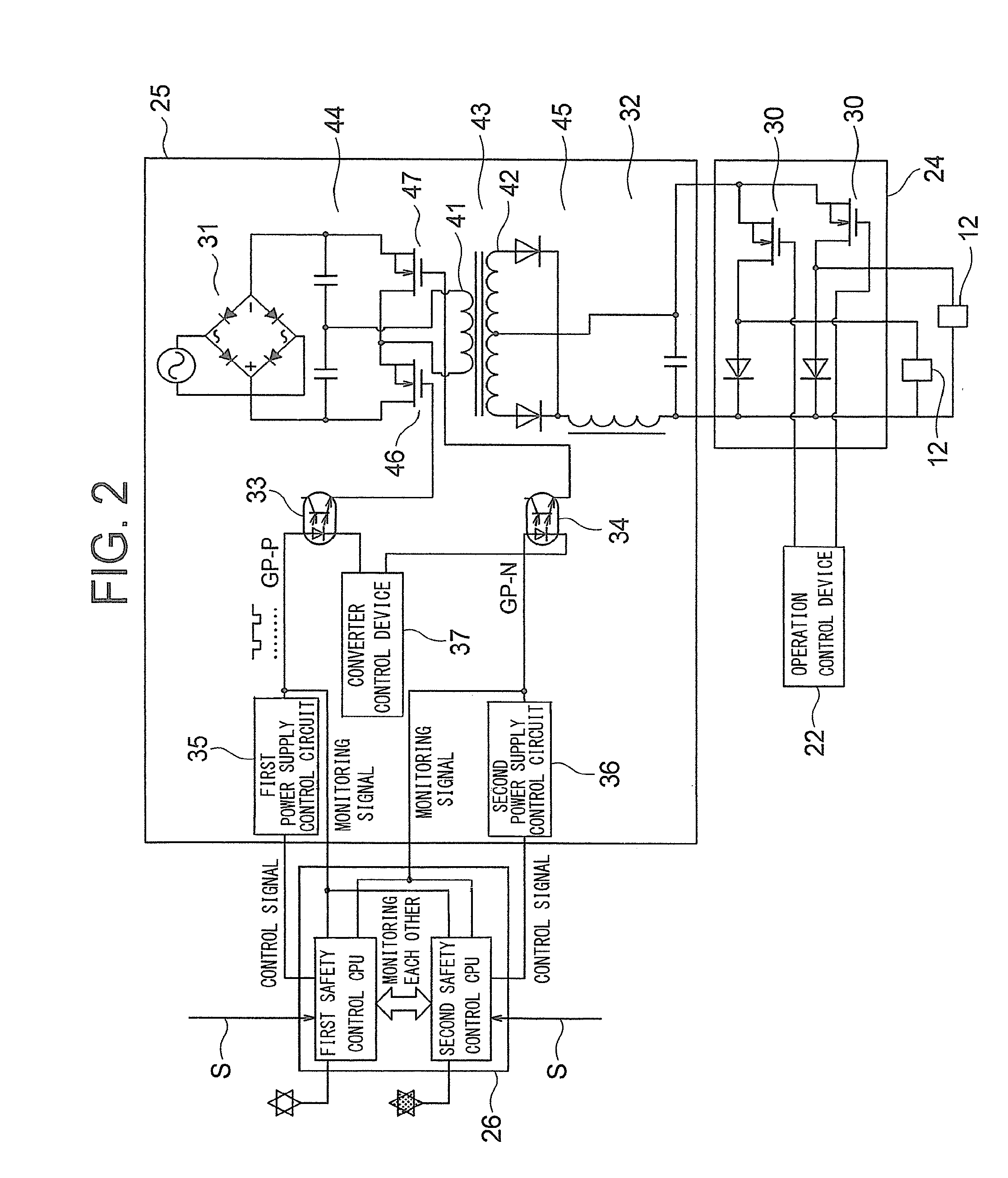
[0054]FIG. 6 is a configuration diagram for illustrating the main parts of an elevator control apparatus according to a second embodiment of the present invention. In FIG. 6, in this example, the DC-DC converter 32 is a full-bridge DC-DC converter. In other words, the primary-side circuit 44 of the DC-DC converter 32 includes a pair of first transistors (transistors on the upper arm (positive electrode) side) 46, and a pair of second transistors (transistors on the lower arm (negative electrode) side) 47. The first and second transistors 46 and 47 are the same as the first and second transistors 46 and 47 in the first embodiment.

[0055]Further, the brake power supply device 25 includes a pair of first photocouplers 33 for outputting drive signals (gate drive signals) to the pair of first transistors 46 in synchronization with each other, and a pair of second photocouplers 34 for outputting drive signals (gate drive signals) to the pair of second transistors 47 in synchronization with...


PUM


Abstract

In an elevator control apparatus, a DC-DC converter including a first switching element and a second switching element is configured to generate power for driving an elevator brake by alternately operating each of the first switching element and the second switching element. A first photocoupler and a second photocoupler are configured to independently operate the first switching element and the second switching element, respectively. A first calculation unit and a second calculation unit are configured to independently control power supply voltages of the first photocoupler and the second photocoupler, respectively.

Description

TECHNICAL FIELD[0001]The present invention relates to an elevator control apparatus for controlling a power supply to an elevator brake.BACKGROUND ART[0002]In general, for an elevator hoisting machine brake, a braking force is produced by cutting the power supply to a brake coil by an electromagnetic switch. When there is only one electromagnetic switch, in a case where an ON failure of the electromagnetic switch occurs, the brake cannot perform a braking operation. Therefore, in order for the brake to reliably perform a braking operation, a plurality of electromagnetic switches are needed.[0003]Hitherto, an elevator brake safety control apparatus has been proposed in which operation of a semiconductor switch in a primary-side circuit of a direct current (DC)-DC converter for supplying power to a brake coil is controlled by a pulse-width modulation controller so that the power supply of the pulse-width modulation controller is cut at a plurality of safety relay contact points when a...

Claims


Application Information

Patent Timeline
Patent Type & Authority Applications(United States)
IPC IPC(8): B66B1/32B66B5/02
CPCB66B5/02B66B1/32B66D5/08B66D5/30
Inventor KUBOTA, TAKEHIKO
Owner MITSUBISHI ELECTRIC CORP
Why Eureka
Try Eureka