
Manipulation apparatus

a technology of manipulating apparatus and manipulation portion, which is applied in the direction of manual control with single controlling member, mechanical control device, instruments, etc., to achieve the effect of reducing contact pressure, reducing friction force, and increasing the ease of manipulation of the manipulating portion

Inactive Publication Date: 2016-07-07
DENSO CORP
View PDF10 Cites 11 Cited by
  • Summary
  • Abstract
  • Description
  • Claims
  • Application Information

AI Technical Summary

Benefits of technology

The present invention provides a manipulation apparatus where a coil is retained by a retaining body and a magnet is retained by a movable body. The coil is energized to generate a Lorentz force that is exerted on the manipulation portion. A repulsive force generation portion reduces the contact pressure between the retaining body and the movable body, thereby increasing the ease of manipulation of the manipulation portion. The repulsive force generation portion may be a magnet or an electromagnet that adjusts the magnitude of the repulsive force by controlling the energization of the magnet. The technical effects of the present invention include facilitating the manipulation of the manipulation portion.

Problems solved by technology

Resultant sliding resistance due to the friction force disturbs manipulation of the manipulation portion on the movable body.

Method used


Image

  • Manipulation apparatus
  • Manipulation apparatus
  • Manipulation apparatus

Examples


Embodiment Construction

[0021][Overall Configuration of Embodiment]

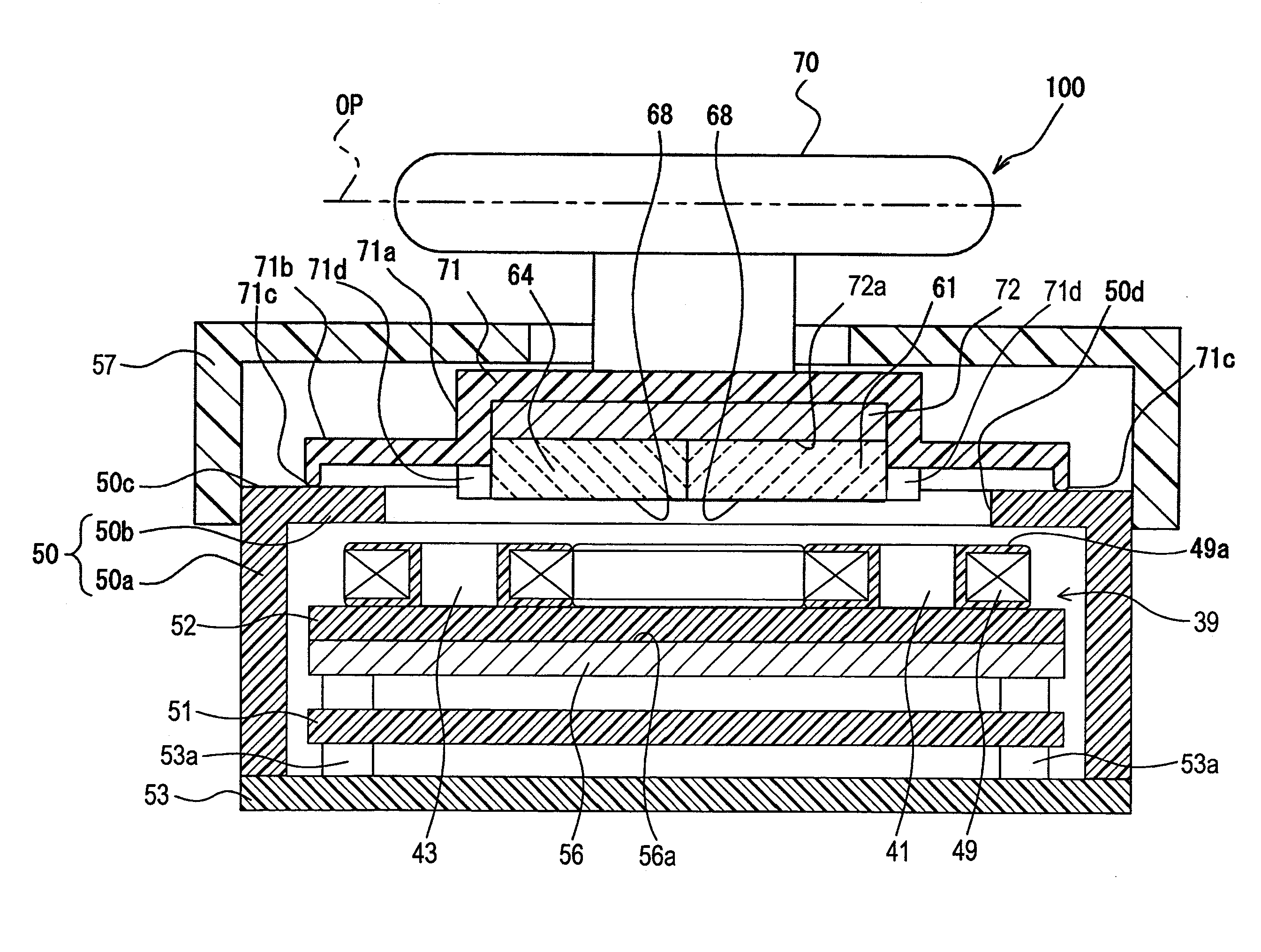
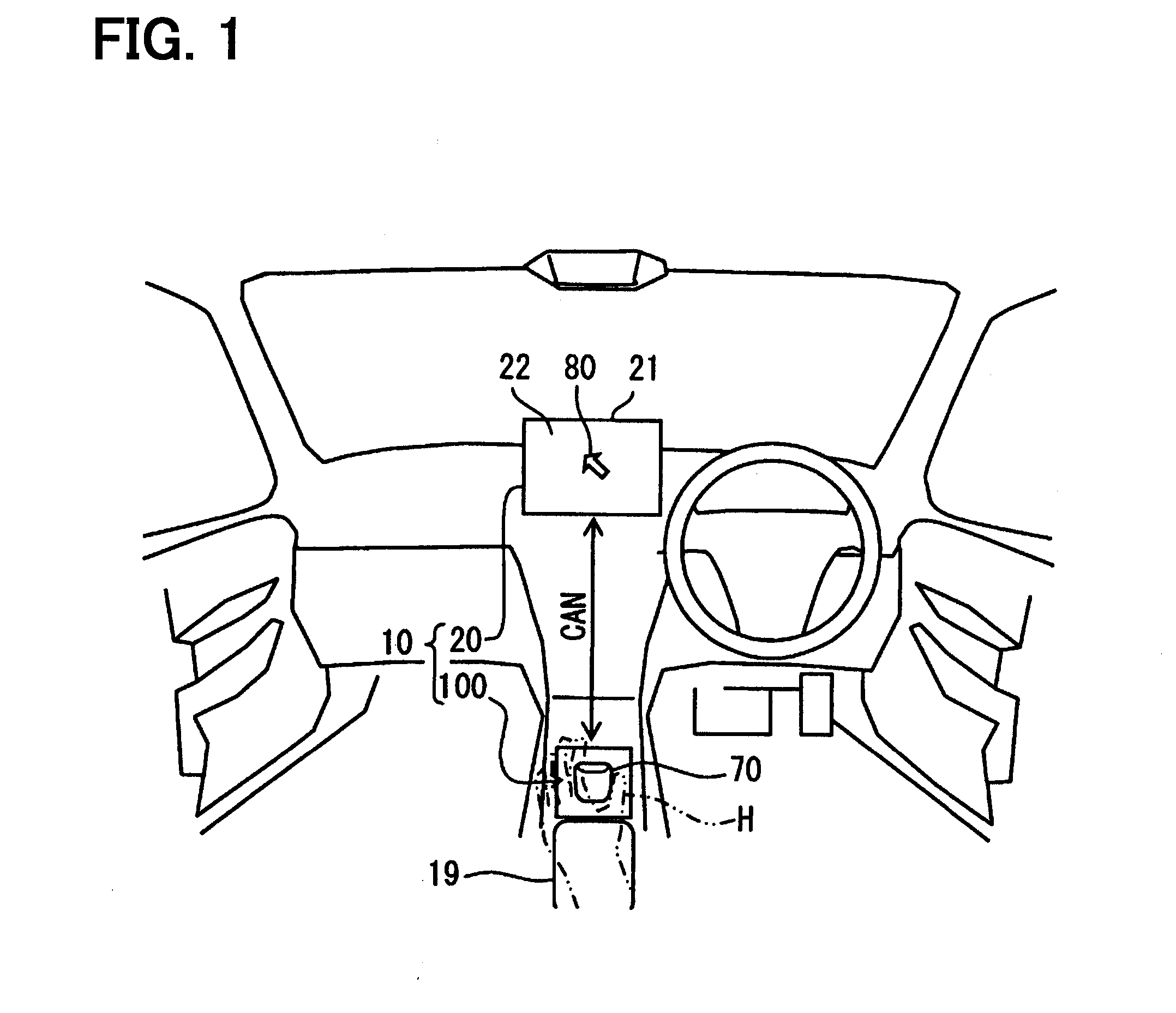
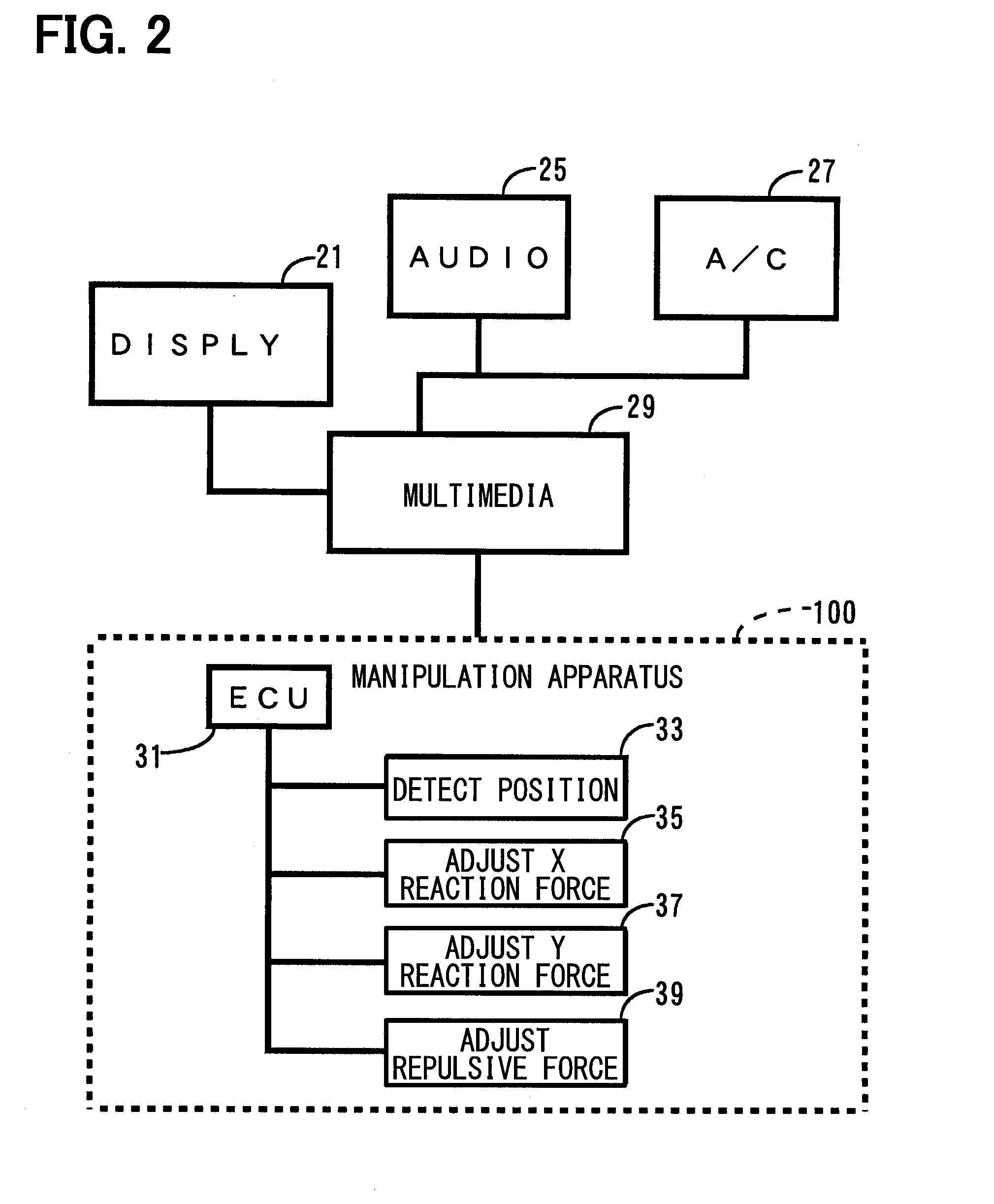
[0022]An embodiment of the present disclosure will now be described with reference to the accompanying drawings. A manipulation apparatus 100 according to the present embodiment is mounted in a vehicle to form a display system 10 together with, for example, a navigation apparatus 20 as in FIG. 1. The manipulation apparatus 100 is mounted on a center console of the vehicle and positioned adjacent to an armrest 19 in such a manner that a manipulation knob 70 is exposed and positioned within easy reach of a hand H of a manipulating person. When a manipulation force is inputted to the manipulation knob 70, for example, by the hand of the manipulating person, the manipulation knob 70 is displaced in the direction of the inputted manipulation force. The navigation apparatus 20 includes a display 21 that is mounted on an instrument panel of the vehicle. A display screen 22 of the display 21 is exposed and oriented toward a driver seat. The display...


PUM


Abstract

A manipulation apparatus that generates a manipulation reaction force on a manipulation knob by energizing a coil disposed between a coil-side yoke and a magnet. A permanent magnet is disposed on a contact portion for a housing of a knob base on which the manipulation knob is mounted. An electromagnet is disposed on a support portion of the housing that supports the contact portion. The electromagnet is energized to generate a repulsive force between the support portion and the contact portion. This reduces a friction force exerted between the support portion and the contact portion.

Description

CROSS REFERENCE TO RELATED APPLICATION[0001]The present application is based on Japanese Patent Application No. 2013-175632 filed on Aug. 27, 2013, the disclosure of which is incorporated herein by reference.TECHNICAL FIELD[0002]The present disclosure relates to a manipulation apparatus to which a manipulation force is inputted.BACKGROUND ART[0003]A manipulation apparatus disclosed in Patent Literature 1 presents a tactile sense to a finger of a manipulating person, e.g., manipulating a tactile sense presentation member as a manipulation portion receiving a manipulation force; the tactile sense is presented using the force applied by an actuator. The actuator includes a magnet and a coil. The magnet is retained on a first yoke plate. The coil is retained by a coil retention member that is capable of moving together with the tactile sense presentation member. Magnetic field lines generated by the magnet are directed to the coil by a second yoke plate that is disposed opposite the mag...

Claims


Application Information

Patent Timeline
Patent Type & Authority Applications(United States)
IPC IPC(8): G06F3/0338G05G5/03G05G1/10G06F3/0354
CPCG06F3/0338G05G1/10G05G5/03G06F3/03548G05G9/047G06F3/016G06F3/033G06F3/0383G06F2203/015
Inventor TACHIIRI, MOTOKI
Owner DENSO CORP
Learn More