Handpiece for treating wounds
- Summary
- Abstract
- Description
- Claims
- Application Information
AI Technical Summary
Benefits of technology
Problems solved by technology
Method used
Image
Examples
first embodiment
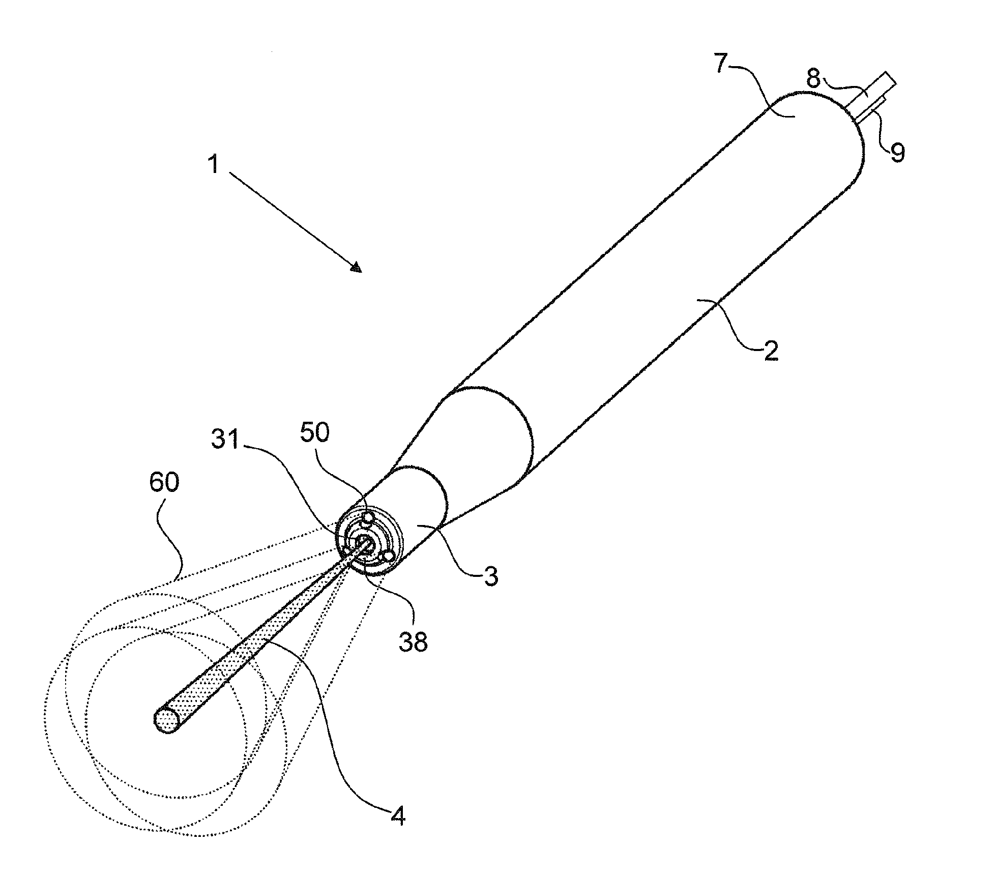
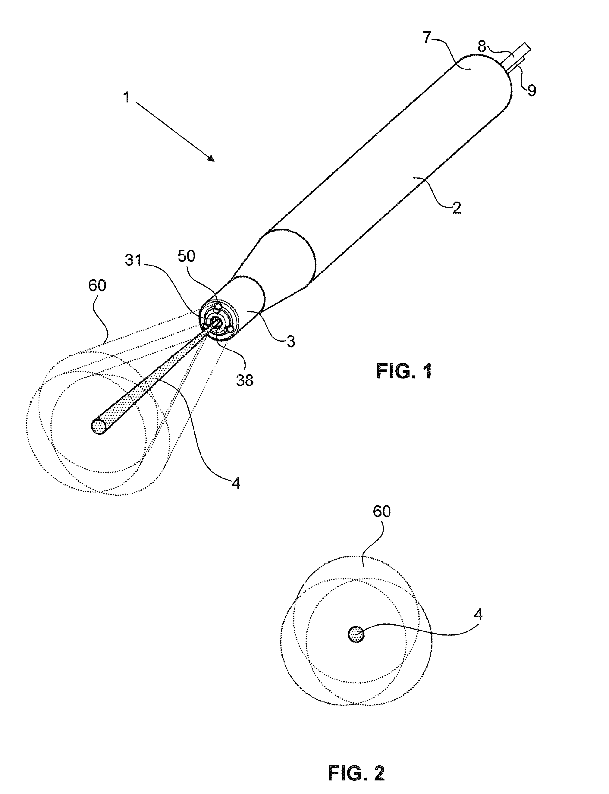
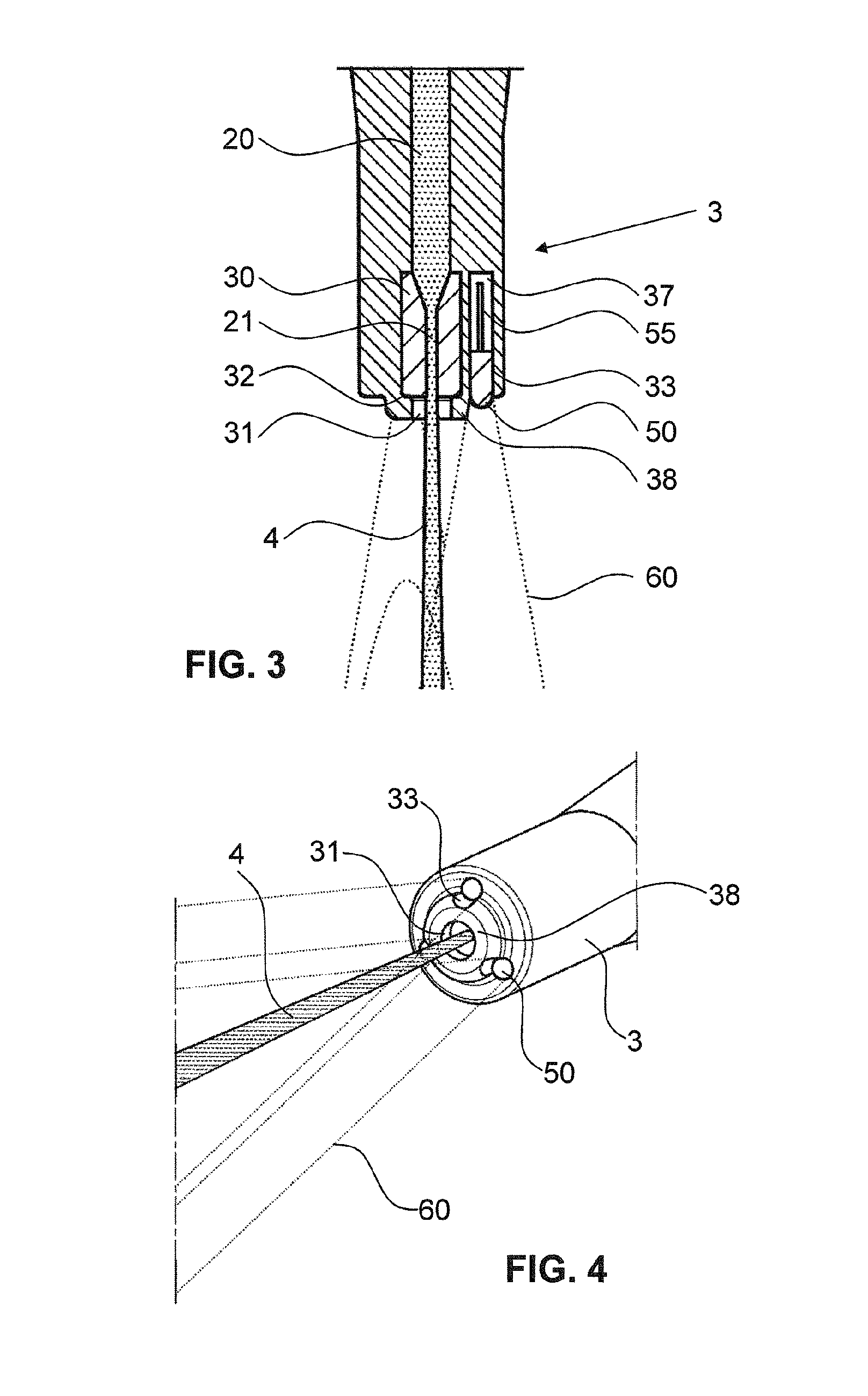
[0063]FIG. 1 shows a perspective illustration of a system according to the invention for treating, in particular for cleansing, wounds with a fluid jet, with first light cones 60 and a fluid jet 4, wherein the system is a handpiece 1 in this embodiment. FIG. 4 shows a perspective illustration of a front end 3 of the handpiece 1. The handpiece 1 has a substantially cylindrical main body 2 with the front end 3 and a rear end 7. The front end 3 has an emergence opening 31 for the emergence of the fluid jet 4. The emergence opening 31 is arranged centrally in a front end face 38 of the handpiece 1. The handpiece 1 is embodied in such a way that the fluid jet 4 emerges from the emergence opening 31 in a manner substantially collinear in relation to the central axis of the main body 2. Three first light sources 50 are preferably arranged at the front end 3. The first light sources 50 are distributed uniformly over the circumference of the front end 3 around the emergence opening 31. The f...
second embodiment
[0071]FIGS. 5, 7 and 8 show illustrations of a system according to the invention for cleansing wounds with a fluid jet, with second light cones 61 and a fluid jet 4, wherein the system is a handpiece 1 in this embodiment. FIG. 6 shows an illustration of an area with the fluid jet 4 illuminated by the handpiece 1 in accordance with FIGS. 5, 7 and 8.
[0072]The second light sources 51 of the second embodiment are UV-C light-emitting diodes, which are arranged on a printed circuit board (PCB).
[0073]The second light sources 51 have a rectangular cross section and they are arranged in corresponding rectangular second recesses 34. In this example, the second light sources 51 are arranged recessed from the front end face 38.
[0074]FIG. 6 shows an illustration of an area with a fluid jet 4 illuminated by the handpiece 1 in accordance with the second embodiment. In contrast to the first embodiment, the second recesses 34 for receiving the second light sources 51 form light-emergence regions whi...
third embodiment
[0078]The handpiece 1 in the third embodiment has a front end 3 expanded in the jet / beam direction for receiving two rectangular third light sources 52. As illustrated, the expansion can be uniform along the circumference; however, in a different exemplary embodiment, it can be embodied in such a way that the expansion is only present in the region of the light sources. The third light sources 52 are UV-C light-emitting diodes, which are integrated in an integrated circuit board (ICB).
[0079]The third light sources 52 have a rectangular cross section and they are arranged in corresponding rectangular third recesses 35. The third light sources 52 are arranged flush with the front end face 38.
[0080]FIG. 10 shows an illustration of an area with the fluid jet 4 illuminated by the handpiece 1 in accordance with the third embodiment. The third recesses 35 for receiving the third light sources 52 form light-emergence regions, which have a substantially rectangular embodiment. The third ligh...
PUM
 Abstract
Description
Claims
Application Information
 - R&D
- Intellectual Property
- Life Sciences
- Materials
- Tech Scout
- Unparalleled Data Quality
- Higher Quality Content
- 60% Fewer Hallucinations
Browse by: Latest US Patents, China's latest patents, Technical Efficacy Thesaurus, Application Domain, Technology Topic, Popular Technical Reports.
© 2025 PatSnap. All rights reserved.Legal|Privacy policy|Modern Slavery Act Transparency Statement|Sitemap|About US| Contact US: help@patsnap.com


