Systems and Methods for Constrained Dozing

a technology of system and method, applied in the field of control of machines, can solve the problems of requiring more time and effort to correct at the back end, affecting overall efficiency and productivity, and involving in the work plan

Inactive Publication Date: 2016-07-14
CATERPILLAR INC
View PDF18 Cites 47 Cited by
  • Summary
  • Abstract
  • Description
  • Claims
  • Application Information

AI Technical Summary

Problems solved by technology

Furthermore, the work plan may often involve repetitive tasks that may be entirely or at least partially automated to minimize operator involvement.
Moreover, seemingly insignificant deviations in the initial few cuts may become compounded and pronounced after several iterations, which may require more time and effort to correct at the back end.
However, excessive reductions in the cutting depth may adversely affect overall efficiency and productivity.
Although Yamamoto may provide some benefit, it is still limited in that it functions in a manner that is localized and blind to the overall work plan.

Method used


Image

  • Systems and Methods for Constrained Dozing
  • Systems and Methods for Constrained Dozing
  • Systems and Methods for Constrained Dozing

Examples


Embodiment Construction

[0017]Although the following sets forth a detailed description of numerous different embodiments, it should be understood that the legal scope of protection is defined by the words of the claims set forth at the end of this patent. The detailed description is to be construed as exemplary only and does not describe every possible embodiment since describing every possible embodiment would be impractical, if not impossible. Numerous alternative embodiments could be implemented, using either current technology or technology developed after the filing date of this patent, which would still fall within the scope of the claims defining the scope of protection.

[0018]It should also be understood that, unless a term is expressly defined herein, there is no intent to limit the meaning of that term, either expressly or by implication, beyond its plain or ordinary meaning, and such term should not be interpreted to be limited in scope based on any statement made in any section of this patent (o...


PUM


Abstract

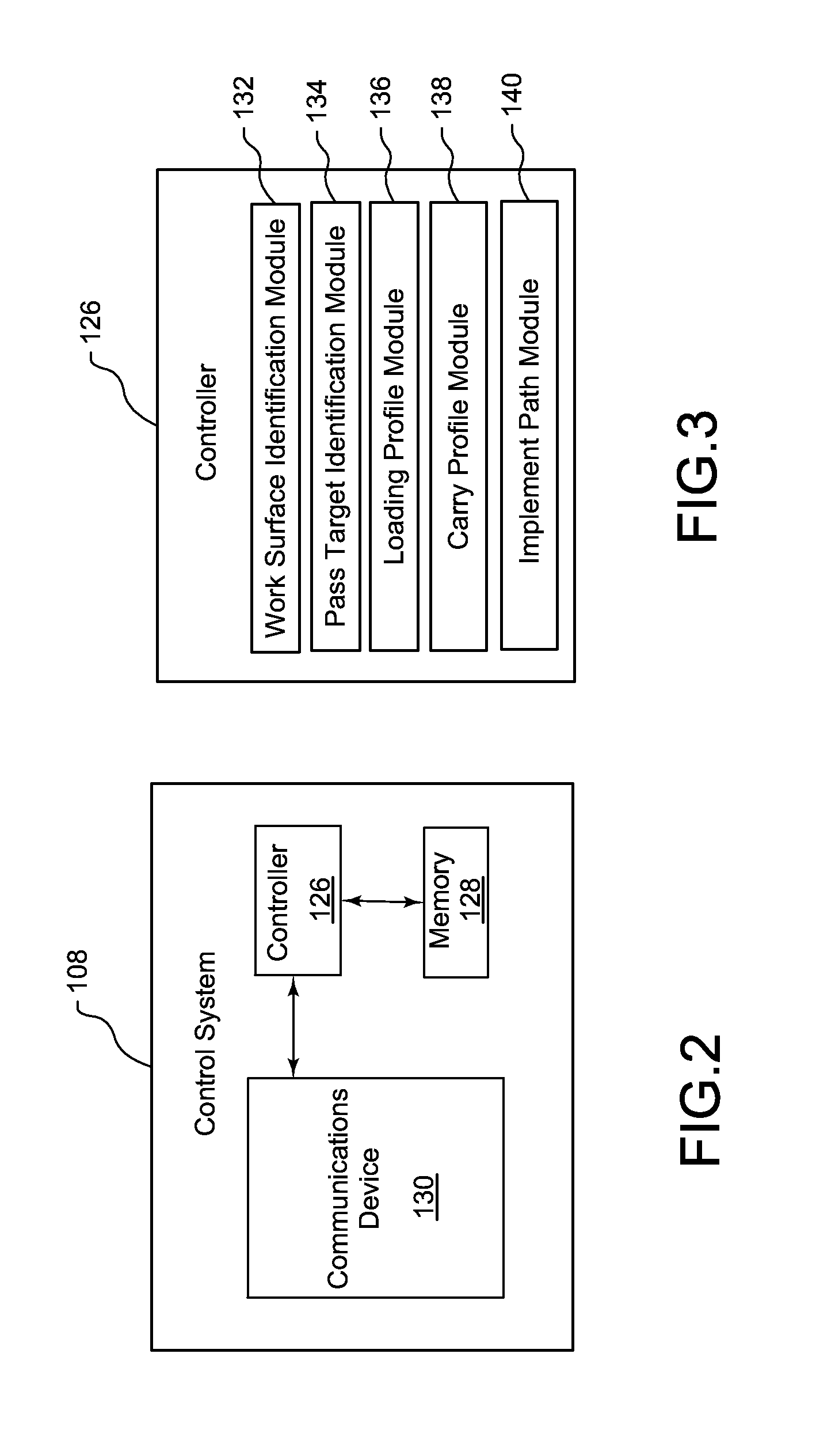
A computer-implemented method for determining an implement path for a machine implement at a worksite is provided. The computer-implemented method may include identifying a work surface and a pass target of the worksite, defining a loading profile based on one or more curves constrained to the work surface and the pass target, defining a carry profile based on the loading profile and the pass target, and designating the loading profile and the carry profile as the implement path.

Description

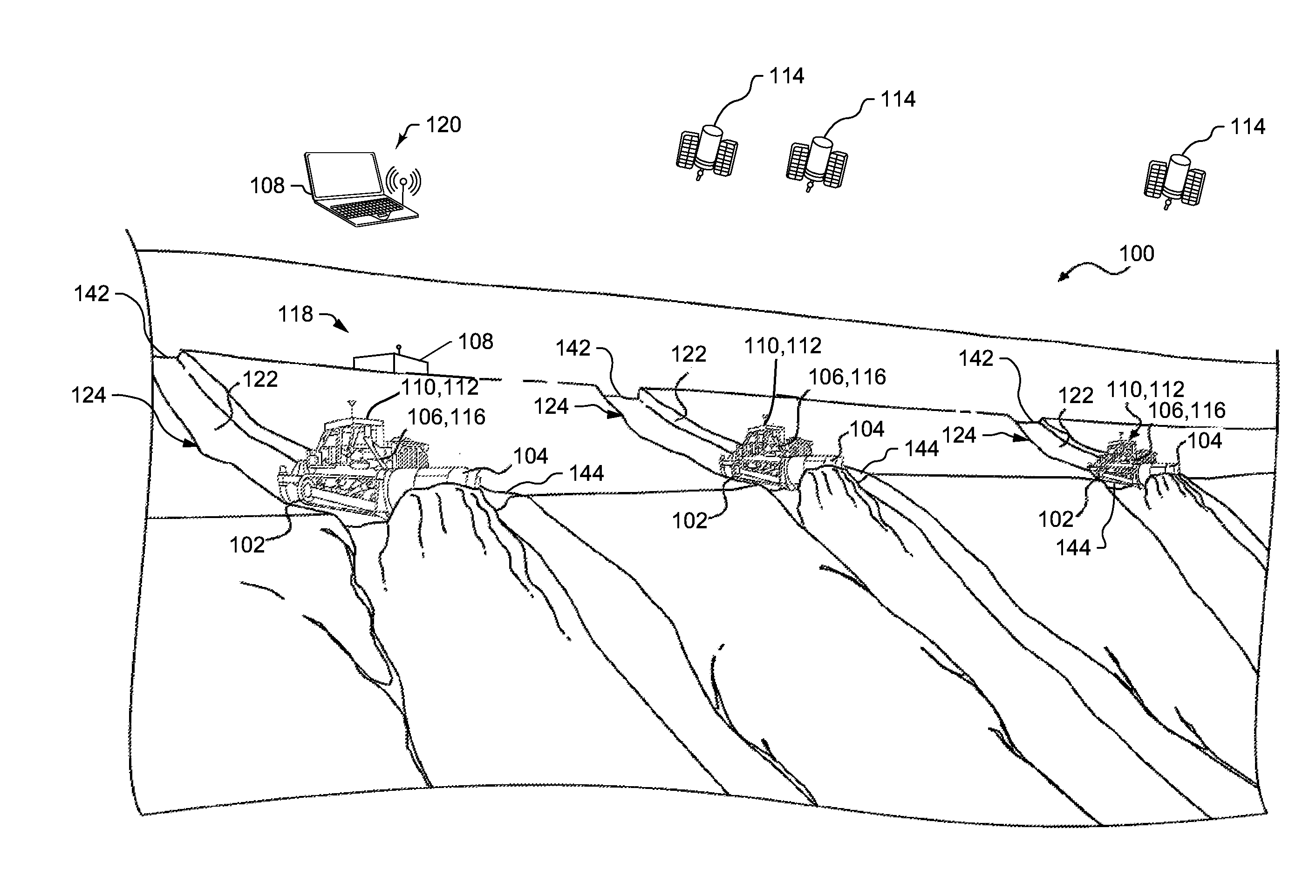
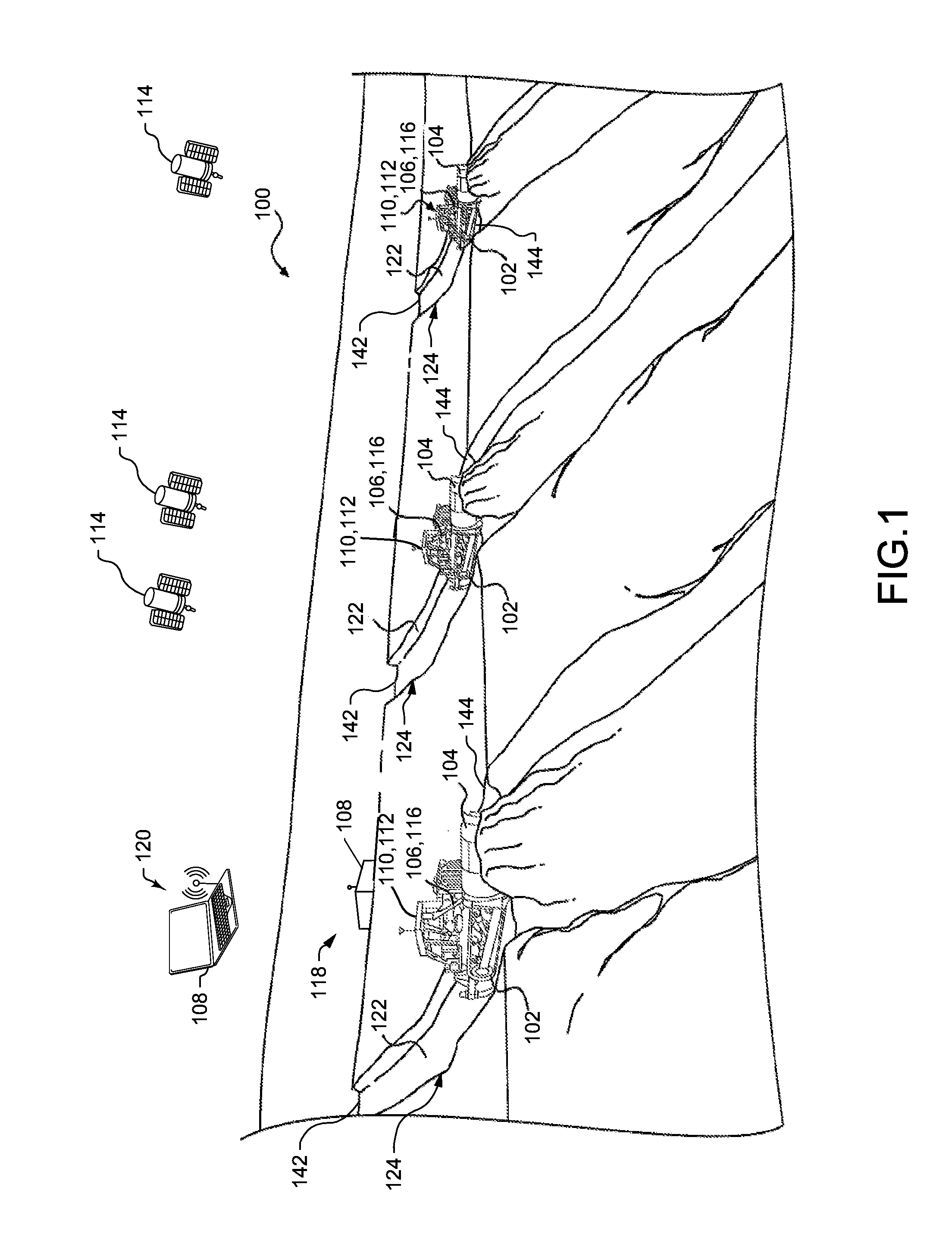
TECHNICAL FIELD[0001]The present disclosure relates generally to controlling machines, and more particularly, to systems and methods for determining blade paths for semi-autonomous and autonomous machines using constrained dozing techniques.BACKGROUND[0002]Machines such as, for example, track-type tractors, dozers, motor graders, wheel loaders, and the like, are used to perform a variety of tasks. For example, these machines may be used to move material and / or alter work surfaces at a worksite. In general, the machines may function in accordance with a work plan for a given worksite to perform operations, including digging, loosening, carrying, and any other manipulation of materials at the worksite. Furthermore, the work plan may often involve repetitive tasks that may be entirely or at least partially automated to minimize operator involvement. Accordingly, the machines may include not only manned machines, but also be autonomous or semi-autonomous vehicles that perform tasks in r...

Claims


Application Information

Patent Timeline
Patent Type & Authority Applications(United States)
IPC IPC(8): E02F9/26E02F9/20
CPCE02F9/261E02F9/2045E02F9/262E02F3/841E02F3/844G05D1/0212G05D2201/0202G06Q10/04
Inventor TAYLOR, MICHAEL A.EDARA, THANDARA K.WEI, MOFELTY, TIMOTHY J.
Owner CATERPILLAR INC
Why Eureka
Try Eureka