Mechanical Locking System For Floor Panels

Active Publication Date: 2016-07-14
CERALOC INNOVATION AB
View PDF6 Cites 90 Cited by
  • Summary
  • Abstract
  • Description
  • Claims
  • Application Information

AI Technical Summary

Benefits of technology

[0060]There may be a smooth transition between the first and the second edge sections along the edge. Al

Problems solved by technology

The 5G system and similar system have been less successful in the low priced market segments.
The major reason is that the cost of the separate tongues and investments in special inserting equipment that is needed to insert a flexible tongue into a displacement groove are regarded as rather high in relation to the rather low price of the floor panels.
All such attempts have failed especially when a floor panel comprises an HDF core.
The failure is based

Method used


Image

  • Mechanical Locking System For Floor Panels
  • Mechanical Locking System For Floor Panels
  • Mechanical Locking System For Floor Panels

Examples


Embodiment Construction

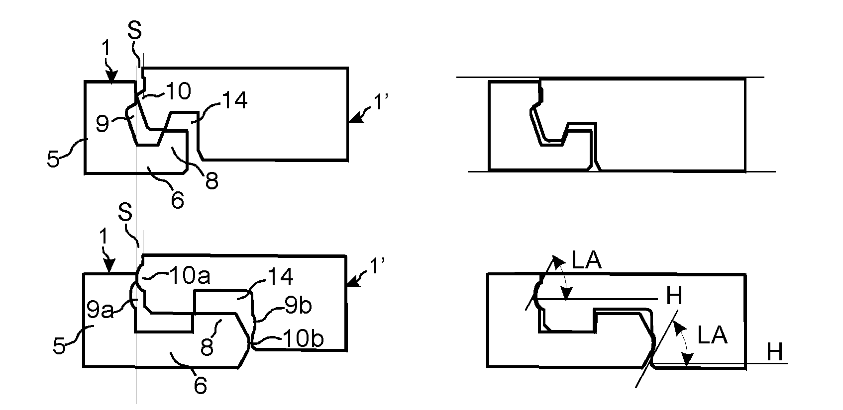
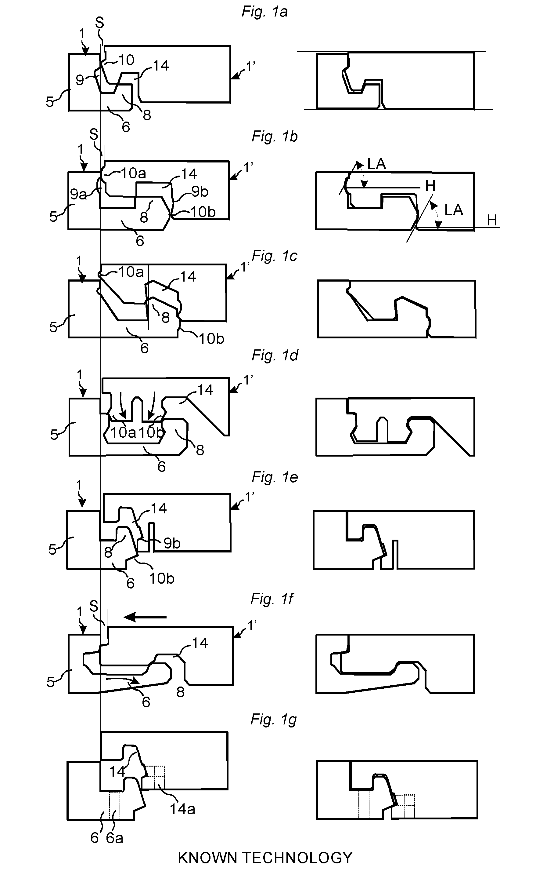
[0141]FIGS. 1a-1f show some examples of known fold down locking systems made in one piece with the core 5 that are intended to lock short edges with a vertical displacement of a second edge of a second panel 1′ against a first edge of a first panel 1. All systems comprise a horizontally protruding strip 6 with a locking element 8 in the first edge of the first panel 1 that cooperates with a locking groove 14 in the second edge of the second panel 1′ and locks the edges of the panels 1, 1′ horizontally. Different methods are used to lock the edges vertically.

[0142]FIG. 1a shows that a small tongue 10 that cooperates with a tongue groove 9 may be used for the vertical locking. Compression of the tongue 10 is required to accomplish the locking. The upper edges are, during the vertical displacement, spaced from each other with a space S that corresponds to the horizontal protrusion of the tongue 10. The adjacent edges must be pulled together during the final stage of the locking. The fr...


PUM


Abstract

Floor panels (1, 1′) are shown, which are provided with a mechanical locking system that may be locked with a vertical displacement of a first panel against a second panel. The locking system includes a flexible strip (6) that during locking bends upwardly or downwardly. The locking system includes a first (7a) and a second (7b) joint edge section with different locking functions. One section provides a horizontal locking and another section provides a vertical locking.

Description

CROSS REFERENCE TO RELATED APPLICATIONS[0001]The present application claims the benefit of Swedish Application No. 1451632-2, filed on Dec. 22, 2014. The entire contents of Swedish Application No. 1451632-2 are hereby incorporated herein by reference in their entirety.TECHNICAL FIELD[0002]The disclosure generally relates to the field of mechanical locking systems for floor panels and building panels. The disclosure includes panels, floorboards, locking systems and production methods.FIELD OF APPLICATION[0003]Embodiments of the present disclosure are particularly suitable for use in floating floors, which are formed of floor panels having one or more upper layers comprising, e.g., thermoplastic or thermosetting material or wood veneer, an inter-mediate core of wood-fibre-based material or plastic material and preferably a lower balancing layer on the rear side of the core. Embodiments of the disclosure may also be used for joining building panels which preferably contain a board mate...

Claims


Application Information

Patent Timeline
IPC IPC(8): E04F15/02B26D3/06E04C2/40
CPCE04F15/02038B26D3/065E04C2/40E04F15/102E04F15/107E04F2201/0161E04F2201/0146E04F2201/0176E04F2201/043E04F2201/042E04F2201/027
Inventor PERVAN, DARKO
Owner CERALOC INNOVATION AB
Why Eureka
Try Eureka