Scroll compressor

Active Publication Date: 2016-07-14
HITACHI JOHNSON CONTROLS AIR CONDITIONING INC
View PDF2 Cites 3 Cited by
  • Summary
  • Abstract
  • Description
  • Claims
  • Application Information

AI Technical Summary

Benefits of technology

[0015]According to the present invention, it is possible to provide a scr

Problems solved by technology

A candidate refrigerant R32 has a problem that its molecular weight is small and leakage loss increases as compared with R410A.
Further, candidate refrigerants R290 and R1234ze have a problem that their volumetric capacity is low as compared with R410A.
However, when using the aluminum-b

Method used


Image

  • Scroll compressor
  • Scroll compressor
  • Scroll compressor

Examples


Example

First Embodiment

Scroll Compressor

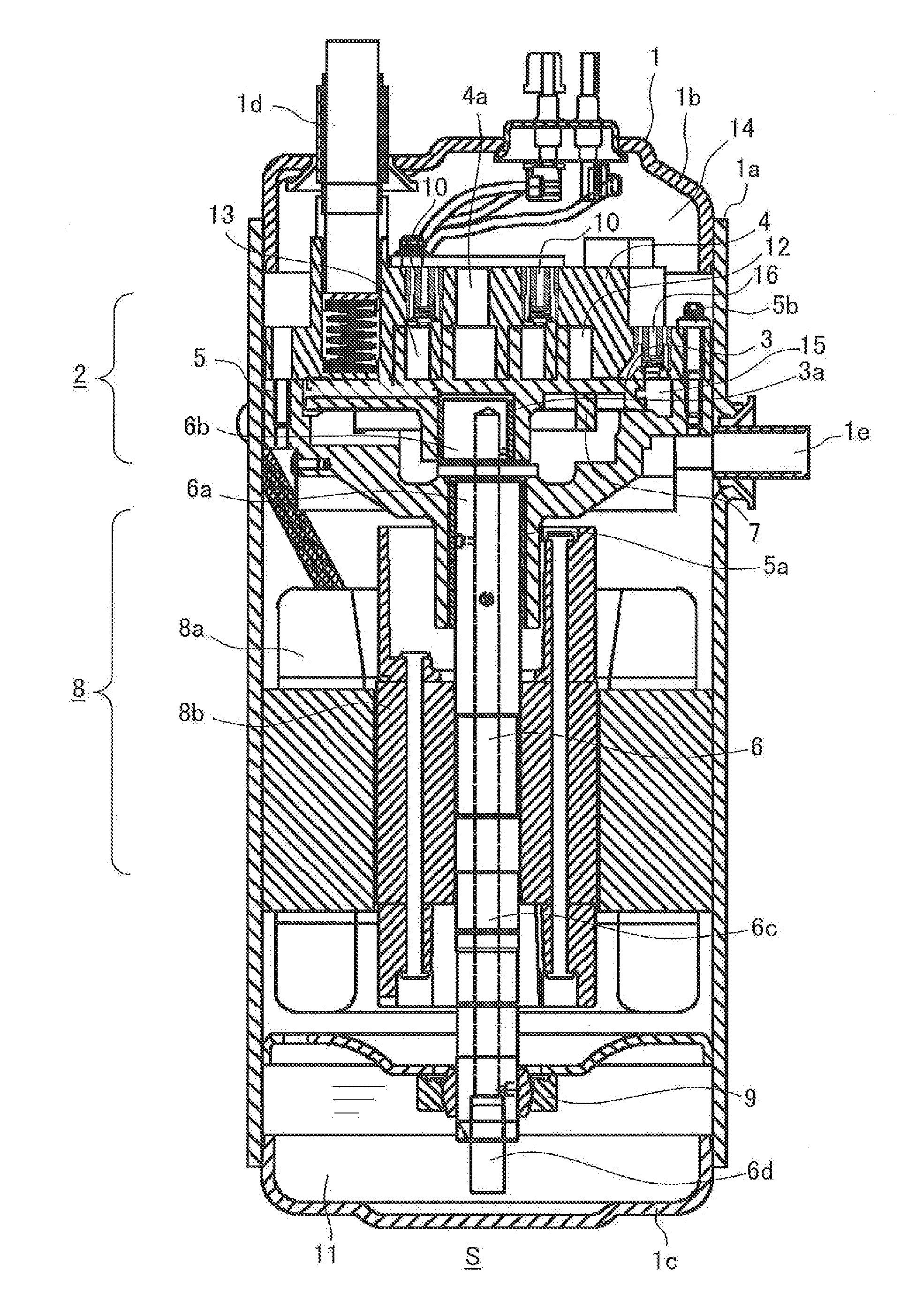
[0027]First, a scroll compressor S according to a first embodiment will be described with reference to FIG. 1. FIG. 1 is a longitudinal sectional view of the scroll compressor S according to the first embodiment.

[0028]As shown in FIG. 1, the scroll compressor S includes a sealed container 1, an orbiting scroll 3, a compression mechanism 2 composed of a fixed scroll 4 and a frame 5, a crankshaft 6, an Oldham ring 7, an electric motor 8, a lower bearing 9 and a release valve device 10.

[0029]The sealed container 1 is configured such that a lid chamber 1b is welded to an upper side of a cylindrical case 1a, and a bottom chamber 1c is welded to a lower side of the cylindrical case 1a. Further, the lid chamber 1b is provided with a suction pipe 1d, and the case 1a is provided with a discharge pipe 1e. The compressor mechanism 2 is disposed at an upper portion in the sealed container 1 composed of the case 1a, the lid chamber 1b and the bottom chamber 1c, a...

Example

Second Embodiment

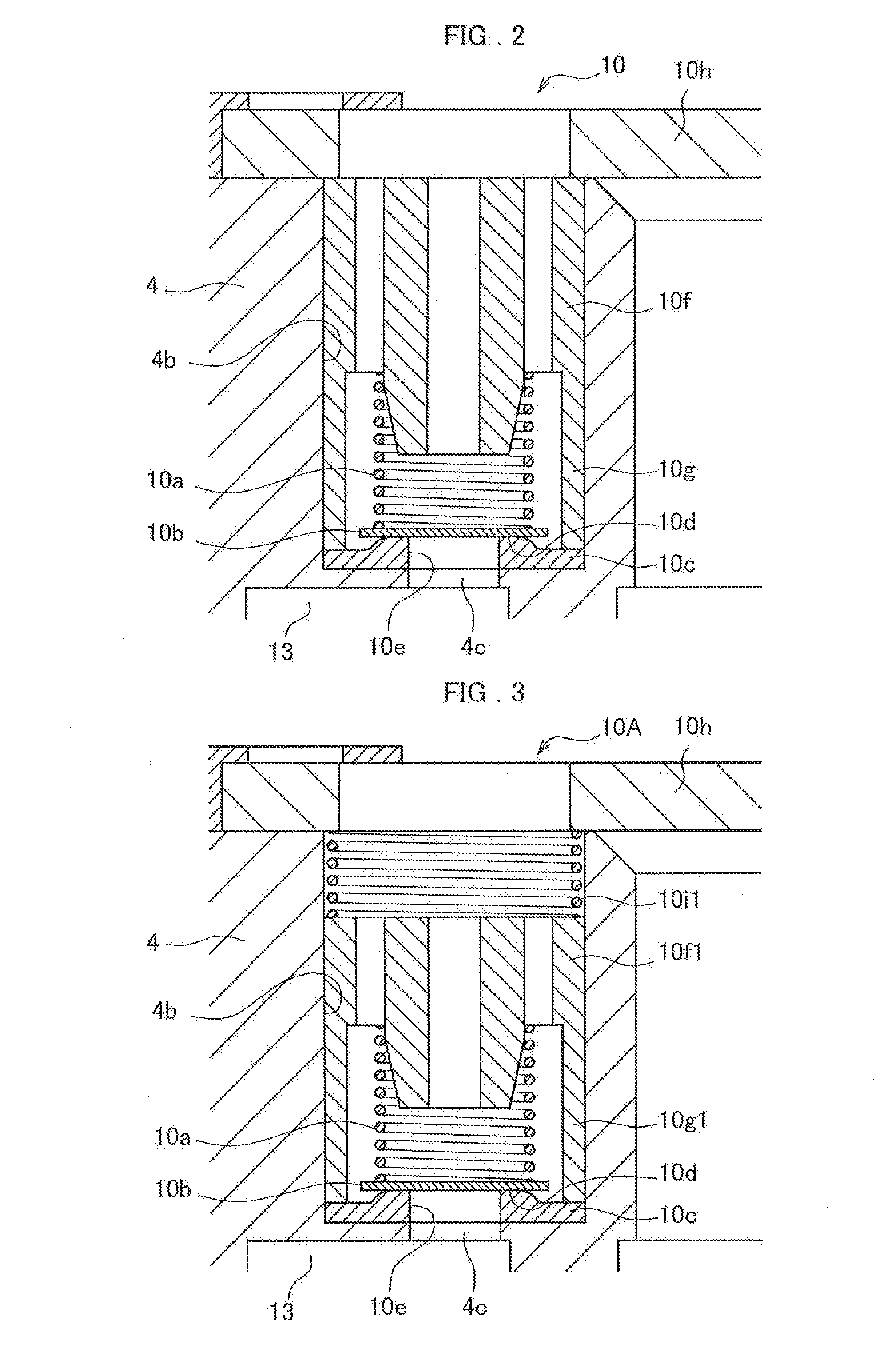
[0063]Next, the scroll compressor S according to a second embodiment will be described. The scroll compressor S according to the second embodiment is different in configuration of a release valve device 10A as compared with the scroll compressor S (see FIG. 1) according to the first embodiment. The other configurations are the same as the first embodiment, and descriptions thereof will be omitted.

[0064]The release valve device 10A included in the scroll compressor S according to the second embodiment will be described with reference to FIG. 3. FIG. 3 is a cross-sectional view of the release valve device 10A according to the second embodiment.

[0065]The release valve device 10A according to the second embodiment included the spring (a first spring) 10a, the valve plate 10b, the valve seat member 10c having the valve seat surface 10d and the release hole 10e, a stopper 10f1 having a holding portion 10g1, a pressing spring (second spring) 10i1, and the retainer 10h.

[00...

Example

Third Embodiment

[0071]Next, the scroll compressor S according to a third embodiment will be described. The scroll compressor S according to the third embodiment is different in configuration of a release valve device 10B as compared with the scroll compressor S (see FIG. 1) according to the first embodiment. The other configurations are the same as the first embodiment, and descriptions thereof will be omitted.

[0072]The release valve device 10B included in the scroll compressor S according to the third embodiment will be described with reference to FIG. 4. FIG. 4 is a cross-sectional view of the release valve device 10B according to the third embodiment.

[0073]The release valve device 10B according to the third embodiment includes the spring (first spring) 10a, the valve plate 10b, the valve seat member 10c having the valve seat surface 10d and the release hole 10e, a stopper 10f2 having a holding portion 10g2, a pressing spring (second spring) 10i2, and the retainer 10h.

[0074]The r...


PUM


Abstract

Provided is a scroll compressor capable of ensuring reliability of a release valve device. The scroll compressor is provided with: an orbiting scroll having an orbiting scroll wrap; a fixed roll having a fixed scroll wrap intermeshing with the orbiting scroll wrap; a release hole formed in the fixed scroll; a housing hole communicating with the release hole and having larger diameter than that of the release hole; a valve seat member which is housed in the housing hole and has a valve seat surface; a valve plate contacting with or separating from the valve seat surface by a pressure difference; a spring for pressing the valve plate against the valve seat surface; a stopper which is equipped with the spring and secures the valve seat member; and a retainer for securing the stopper.

Description

TECHNICAL FIELD[0001]The present invention relates to a scroll compressor.BACKGROUND ART[0002]In the past few years, in the refrigeration and air-conditioning industry, there is a growing movement to change a conventional refrigerant to a refrigerant having a low GWP (Global Warming Potential). Currently, as an alternative refrigerant (a next refrigerant) to R410A widely used in an air conditioner, R32, R290, R1234ze and the like are raised as candidate refrigerants.[0003]A candidate refrigerant R32 has a problem that its molecular weight is small and leakage loss increases as compared with R410A. Further, candidate refrigerants R290 and R1234ze have a problem that their volumetric capacity is low as compared with R410A. As a solution to these problems, it is effective to reduce a displacement volume of a compressor and to operate the compressor in high-speed rotation.[0004]However, when operating a scroll compressor in high-speed rotation, there is a possibility that by centrifugal...

Claims


Application Information

Patent Timeline
IPC IPC(8): F04C29/12F04C18/02
CPCF04C29/124F04C18/0292F04C18/0215F04C18/0261F04C23/008F04C28/26
Inventor KOUNO, TAKESHINOZAKI, TSUTOMUYANAGASE, YUUICHI
Owner HITACHI JOHNSON CONTROLS AIR CONDITIONING INC
Why Eureka
Try Eureka