
High voltage ceramic electric heating body

Pending Publication Date: 2022-02-03
CHONGQING LE MARK CERAMIC TECH CO LTD
View PDF0 Cites 0 Cited by
  • Summary
  • Abstract
  • Description
  • Claims
  • Application Information

AI Technical Summary

Benefits of technology

The present invention provides a high-voltage ceramic electric heating element that can effectively control its heating region during use, ensuring reliable ignition and a success rate of 100%. The heating element is designed to have better quality at its head portion, the farthest end during slip casting, by controlling the temperature zones and improving its service life. The heating element also has a smooth surface, compact structure, and high strength of more than or equal to 20 KG.

Problems solved by technology

In order to form a larger resistance, a resistor needs to be manufactured larger in volume, and a large-volume resistance layer has a large temperature zone, so that the heating region is not easily controlled.
However, during actual use, according to user's responses, uncertain up-and-down displacements of the temperature zones of the existing high-voltage ceramic electric heating elements occur along with the increase of use, resulting in the fact that the ignition reliability cannot be effectively ensured after a period of use.
Furthermore, the existing high-voltage ceramic electric heating elements have a short service life, which is shorter than or equal to 100 H, in a continuous energized state and have a service life of less than or equal to 5000 times in a flame combustion chamber, and have poor surface quality, a loose structure, and low strength of lower than or equal to 20 KG.

Method used


Image

  • High voltage ceramic electric heating body
  • High voltage ceramic electric heating body
  • High voltage ceramic electric heating body

Examples


embodiment 1

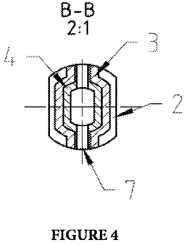
[0027] as shown in FIGS. 1 to 4, a high-voltage ceramic electric heating element, comprising a body, the body being hollow and having an open trailing portion, and a notch being provided on the body in the axial direction and extending through from left to right; a temperature control region is provided at a position on an outer resistance layer of the body, and the cross sectional area of the temperature control region is smaller than the cross sectional area of the body.

[0028]The temperature control region can be provided at any position of an outer resistance layer of the body, for example, at the middle portion, the head portion, or the trailing portion of the body. However, in this embodiment, in consideration of process conditions, the temperature control region is preferably provided at a head portion of the body. The axial length and the cross sectional area of the temperature control region can be set according to actual situations.

[0029]In this embodiment, the cross sectio...

embodiment 2

[0033] as shown in FIGS. 1 to 4, a high-voltage ceramic electric heating element, comprising a body, the body being hollow and having an open trailing portion, and a notch being provided on the body in the axial direction and extending through from left to right; a temperature control region is provided at a position on an outer resistance layer of the body, and the cross sectional area of the temperature control region is smaller than the cross sectional area of the body.

[0034]The temperature control region can be provided at any position of an outer resistance layer of the body, for example, at the middle portion, the head portion, or the trailing portion of the body. However, in this embodiment, in consideration of process conditions, the temperature control region is preferably provided at a head portion of the body. The axial length and the cross sectional area of the temperature control region can be set according to actual situations.

[0035]In this embodiment, the cross sectio...

embodiment 3

[0041] as shown in FIGS. 1 to 4, this embodiment provides a four-layered high-voltage ceramic electric heating element, comprising a body 9. The body has, from inside to outside, an inner insulation enhancement layer 4, an inner insulating layer 3, an outer resistance layer 2, and an electrically conductive layer 1. The inner insulation enhancement layer, the inner insulating layer, and the outer resistance layer cover the entirety of the body, and the electrically conductive layer covers a trailing portion of the outer resistance layer, a trailing end of the electrically conductive layer provides positive and negative electrode positions 5.

[0042]The head portion of the ceramic electric heating element is of a flat shape formed by inwardly inclining left and right sides, and the flat shape is the temperature control region 8. In this embodiment, the cross sectional area of the temperature control region is 80% of the cross sectional area of the body, and the axial length of the temp...


PUM


Abstract

A high-voltage ceramic electric heating element, comprising a body (9), the body (9) being hollow and having an open trailing portion, and a notch (7) being provided on the body (9) in the axial direction and extending through from left to right; a temperature control region (8) is provided at a position on an outer resistance layer (2) of the body (9), and the cross sectional area of the temperature control region (8) is smaller than the cross sectional area of the body (9). Using the high-voltage ceramic electric heating element can improve the ignition reliability and the service life.

Description

[0001]This patent application is a 35 U.S.C. § 371 national stage application based on and claiming propriety to PCT / CN2019 / 117043, filed on Nov. 11, 2019, which in turn claims priority to Chinese Patent Application CN 201811548834.0, filed on Dec. 18, 2018, the disclosures of which are incorporated by reference in theor entireties.TECHNICAL FIELD[0002]The present disclosure relates to an electric heating element, and in particular to a high-voltage ceramic electric heating element having a layered structure.BACKGROUND[0003]In the prior art, ceramics can be used for an electric heating element for ignition, e.g. ignition of motor vehicle engines, gas ignition, etc. During use, a ceramic electric heating element has the advantages of high reliability and stability and a long service life.[0004]The existing ceramic electric heating elements are divided into high-voltage ceramic electric heating elements and low-voltage ceramic electric heating elements depending on the voltage that ca...

Claims


Application Information

Patent Timeline
IPC IPC(8): H05B3/14H05B3/48
CPCH05B3/141H05B2203/027H05B3/48H05B3/10H05B3/44H05B3/06F23Q7/001H05B3/46F23Q7/10
Inventor LEIGH, PETER
Owner CHONGQING LE MARK CERAMIC TECH CO LTD
Learn More