Ultrasonic transceiver

Pending Publication Date: 2022-03-17
PANASONIC INTELLECTUAL PROPERTY MANAGEMENT CO LTD
View PDF0 Cites 0 Cited by
  • Summary
  • Abstract
  • Description
  • Claims
  • Application Information

AI Technical Summary

Benefits of technology

[0009]With this configuration, electrical continuity can be secured even when a proportion of the conductive particles in the adhesive layer is small, and a predetermined adhesive strength can be secured by increasing a proportion of the adhesive. In addition, since the conductive particles serve as spacers, the thickness of the adhesive layer can be set to a constant thicknes

Problems solved by technology

However, in the conventional configuration, since an electrode of piezoelectric body 16 and metal case 14 are bonded with non-conductive adhesive 17, electrical continuity becomes unstable, and thus characteristics of an ultrason

Method used


Image

  • Ultrasonic transceiver
  • Ultrasonic transceiver

Examples


Example

[0014]Hereinafter, an embodiment of the present disclosure will be described with reference to the drawings. Note that the present disclosure is not limited to the exemplary embodiment.

Exemplary Embodiment

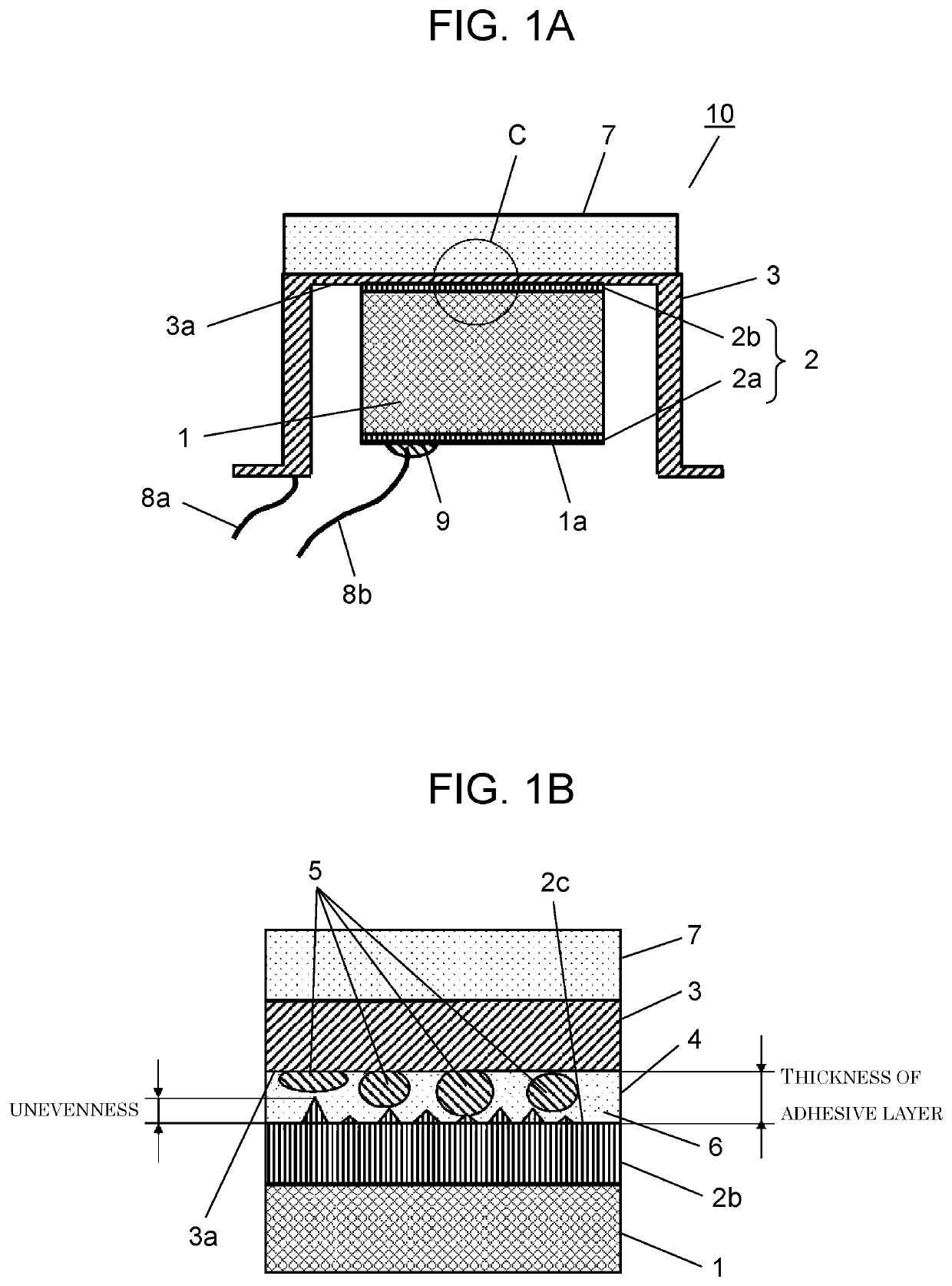
[0015]FIG. 1A is a cross-sectional view of an ultrasonic transceiver in an exemplary embodiment. FIG. 1B is an enlarged schematic view of portion C in FIG. 1A.

[0016]In FIGS. 1A and 1B, ultrasonic transceiver 10 includes piezoelectric body 1, case 3 having conductivity, and acoustic matching layer 7 bonded to an ultrasonic transmission surface of case 3. Piezoelectric body 1 is bonded to inner surface 3a of case 3 by adhesive member 4.

[0017]Adhesive member 4 includes adhesive 6 and conductive particles 5 mixed in adhesive 6, and is formed in a sheet shape. Adhesive 6 is, for example, an epoxy resin-based adhesive, and conductive particles 5 are, for example, resin particles whose surfaces are subjected to Ni—Au plating.

[0018]Piezoelectric body 1 includes electrode 2 formed by firing...


PUM

PropertyMeasurementUnit
Thicknessaaaaaaaaaa
Particle diameteraaaaaaaaaa
Thicknessaaaaaaaaaa

Abstract

An ultrasonic transceiver includes a case having conductivity, a piezoelectric body having a piezoelectric electrode, and an adhesive member that bonds the case to the piezoelectric body. The adhesive member includes an adhesive and conductive particles, and secures electrical continuity between the case and the piezoelectric electrode. An adhesive layer formed of the adhesive member provided between the case and the piezoelectric electrode has a thickness equal to or less than a particle diameter of the conductive particles.

Description

TECHNICAL FIELD[0001]The present disclosure relates to an ultrasonic transceiver that transmits and receives ultrasonic waves using a piezoelectric body.BACKGROUND ART[0002]Conventionally, in this type of ultrasonic transceivers, a piezoelectric body and a case are bonded with a non-conductive adhesive in order to secure adhesive strength (for example, PTL 1).[0003]FIG. 2 illustrates a conventional ultrasonic transceiver. As illustrated in FIG. 2, conventional ultrasonic transceiver 20 includes metal case 14, piezoelectric body 16, and adhesive 17 that connects piezoelectric body 16 and case top inner wall 15 of metal case 14.CITATION LISTPatent Literature[0004]PTL 1: Unexamined Japanese Patent Publication No. 2003-270013SUMMARY OF THE INVENTION[0005]However, in the conventional configuration, since an electrode of piezoelectric body 16 and metal case 14 are bonded with non-conductive adhesive 17, electrical continuity becomes unstable, and thus characteristics of an ultrasonic tran...

Claims


Application Information

Patent Timeline
IPC IPC(8): C09J9/02H04R17/00
CPCC09J9/02G01S15/931H04R17/00B06B1/067C09J11/00C08K2201/001C08K7/16H10N30/877H10N30/88H10N30/073
Inventor ISHIZAKI, YUDAINAGAHARA, HIDETOMO
Owner PANASONIC INTELLECTUAL PROPERTY MANAGEMENT CO LTD
Why Eureka
Try Eureka