Fluid dynamic pressure bearing device, spindle motor provided with the fluid dynamic pressure bearing device, and recording disk drive device

Inactive Publication Date: 2010-02-16
MINEBEA CO LTD
View PDF14 Cites 0 Cited by
  • Summary
  • Abstract
  • Description
  • Claims
  • Application Information

AI Technical Summary

Benefits of technology

[0031]With this structure, a smaller recording disk drive device with high reliability can be obtained.
[0032]Thus, in exemplary embodiments of a fluid dynamic pressure bearing device according to this invention, a reflux path formed on the step portion surface of a substantially L-shaped inner circumferential large-diameter step portion of the bearing member-side annular member is a reflux path formed by an open groove, hereafter also called a reflux groove. When the shaft member-side annular member vertically fluctuates at the time of relative rotation between the shaft member and the bearing member, lubricant can easily and promptly flow through the reflux path. The reflux path may allow lubricant to flow outwardly, in a radial direction or in a direction inclined from the radial direction, between the adjacent convex surface portions, from a micro gap formed between the small-diameter outer circumferential surface portion of the shaft member-side annular member and the small-diameter inner circumferential surface portion of the bearing member-side annular member. The lubricant may merge in a communication groove formed continuously with micro gaps between the large-diameter portion inner circumferential surface and the plurality of the convex surface portions

Problems solved by technology

In the case of portable devices, vibration and shock due to carrying frequently occur.
For example, there are many chances for vibration and shock to occur during motor rotation while the portable devices are being used during transportation on trains, planes, vehicles, etc.
When the external diameter dimension is enlarged, there is a problem in that the torque increases.
However, if vibration or shock becomes signific

Method used


Image

  • Fluid dynamic pressure bearing device, spindle motor provided with the fluid dynamic pressure bearing device, and recording disk drive device
  • Fluid dynamic pressure bearing device, spindle motor provided with the fluid dynamic pressure bearing device, and recording disk drive device
  • Fluid dynamic pressure bearing device, spindle motor provided with the fluid dynamic pressure bearing device, and recording disk drive device

Examples


Example

[0058]The following explains a first embodiment (embodiment 1) according to the invention.

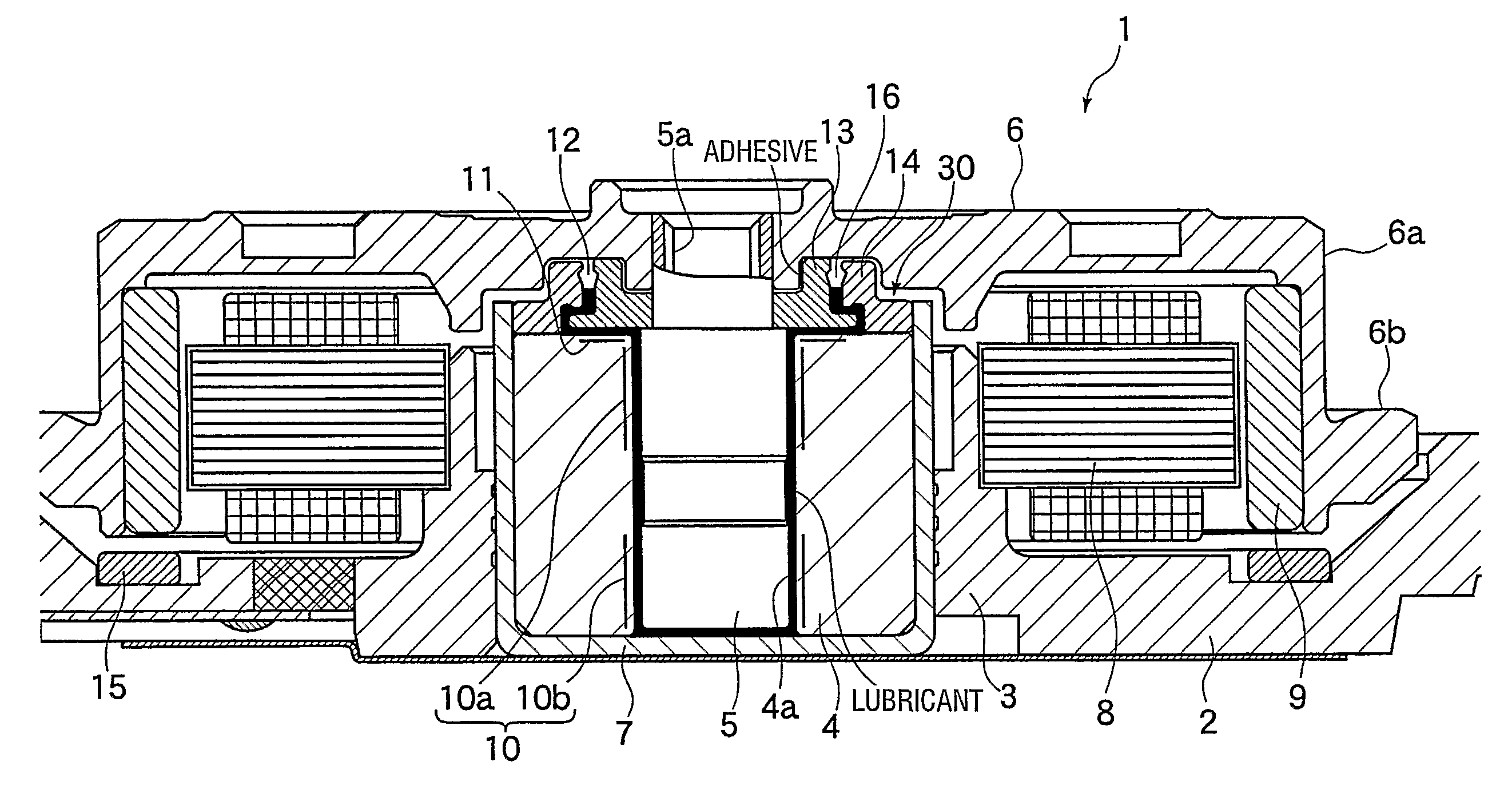
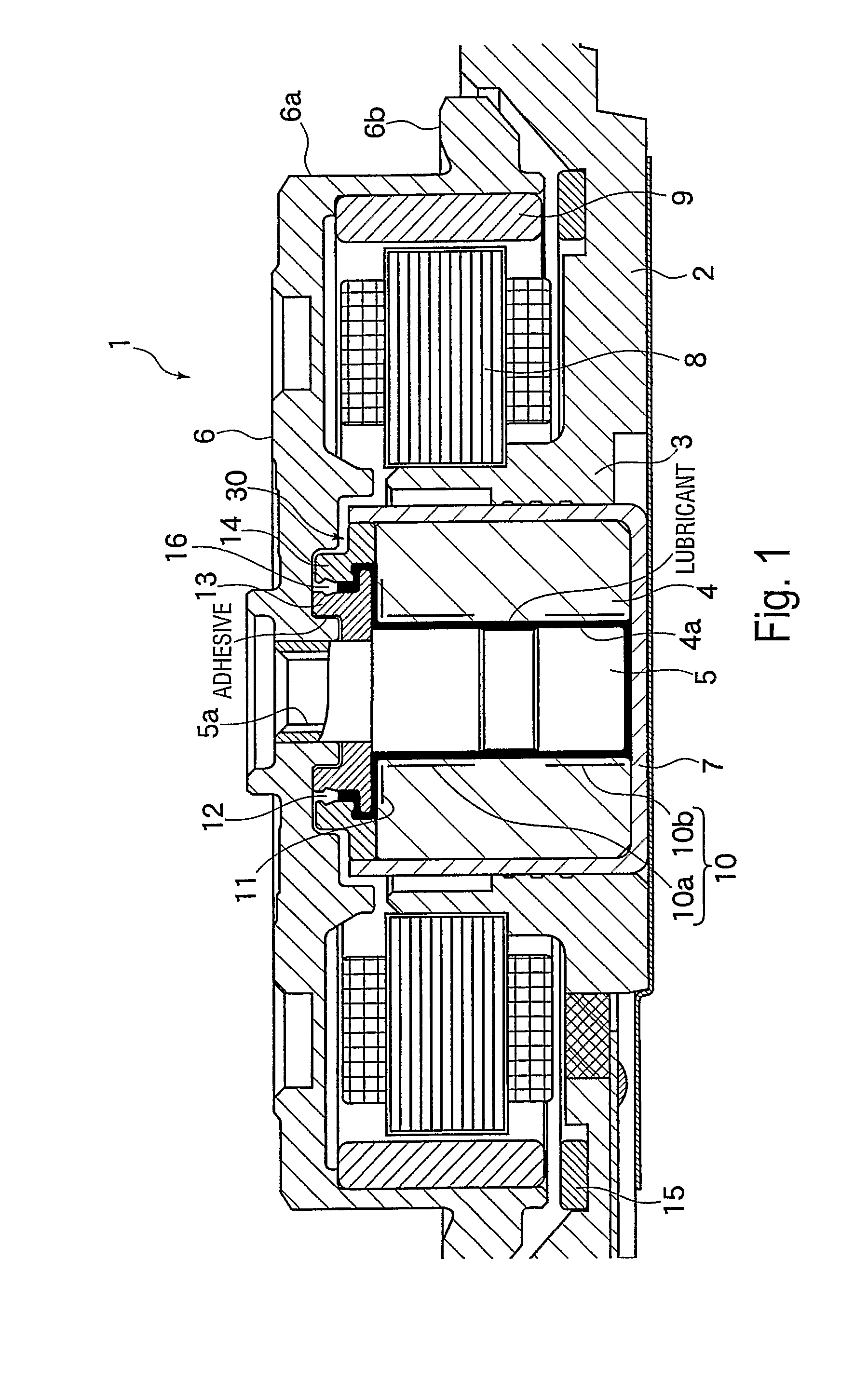
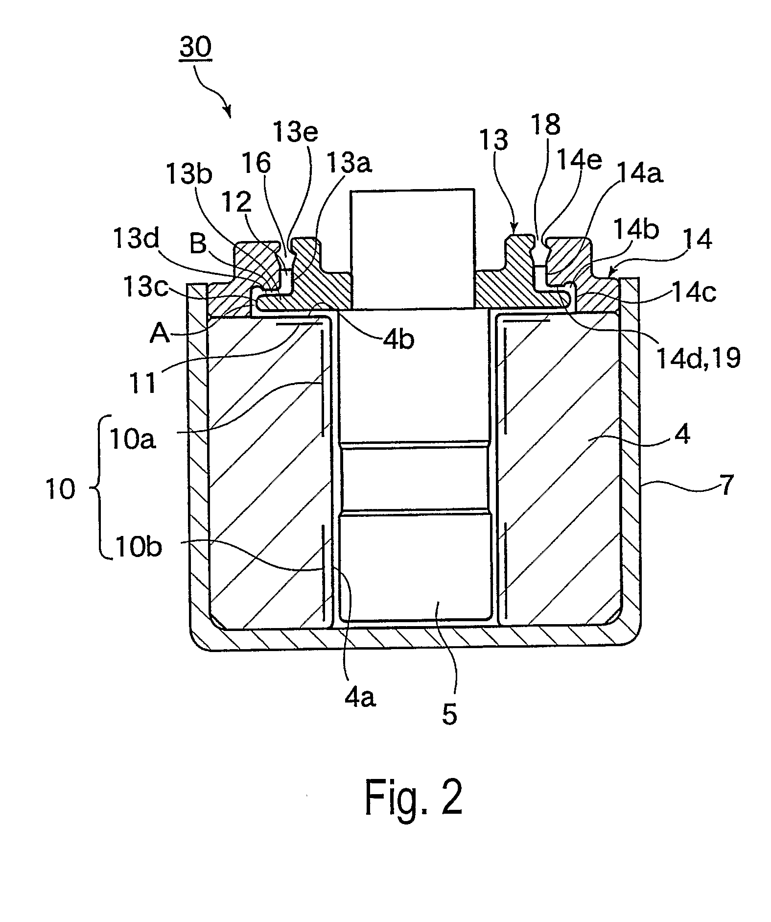
[0059]FIG. 1 is a vertical cross-sectional view of a spindle motor to which a fluid dynamic pressure bearing device of embodiment 1 is applied. FIG. 2 is an enlarged view of the fluid dynamic pressure bearing device. FIG. 3 illustrates a bottom surface of a bearing member-side annular member that is mounted to the bearing member of the fluid dynamic pressure bearing device. FIG. 4 is a cross section taken along line 4-4 of FIG. 3.

[0060]A spindle motor 1 to which a fluid dynamic pressure bearing device 30 of embodiment 1 is applied may be a spindle motor used as a drive source of a magnetic disk drive device. As shown in FIG. 1, a closed-bottom cylindrical member 7, in which a tubular sleeve forming a bearing member 4 of the fluid dynamic pressure bearing device 30 is engaged and fixed, is engaged with a cylindrical bearing holding portion 3 that is arranged perpendicular to the center portion o...

Example

[0080]In the case of the embodiment 1, formation of the convex surface portions 19 and the concave surface portions 20 can be easily processed. Additionally, the reflux of lubricant around the periphery of the convex surface portions 19 and in the direction of the micro gap A from the deepest locations around the convex surface portions 19 has a characteristic such that there is no restriction due to the rotation direction of the shaft member 5. In other words, the shaft member 5 may be rotated in either direction. In addition, the size of the concave surface portions 20 on the step portion surface 14d can be formed so as to be sufficiently large with respect to the convex surface portions 19. In this case, the lubricant amount in the concave surface portions 20 and the communication groove C portion is slightly larger than the lubricant amount in the micro gap B between the convex surface portions 19 and the rim portion upper surface 13d. Therefore, even if a pumping operation is g...

Example

[0082]The following explains a second embodiment (embodiment 2).

[0083]FIG. 5 illustrates a bottom surface of a bearing member-side annular member mounted to a bearing member of a fluid dynamic pressure bearing device of embodiment 2. FIG. 6 is a cross section taken along line 6-6 of FIG. 5.


PUM


Abstract

A fluid dynamic pressure bearing device includes a shaft member (5) and a bearing member (41), at least one of the shaft member or the bearing member being rotatable with respect to the other. A shaft member-side annular member (13) is fixed with respect to the shaft member. The shaft member-side annular member includes a large-diameter rim portion and a small-diameter outer circumferential surface portion. A bearing member-side annular member (14) is fixed with respect to the bearing member. The bearing member-side annular member includes an inner circumferential large-diameter step portion, and a small-diameter inner circumferential surface portion. A plurality of convex surface portions are formed either on a surface of the inner circumferential large-diameter step portion facing the large-diameter rim portion of the shaft member-side annular member, or on a surface of the large-diameter rim portion of the shaft member-side annular member facing a surface of the inner circumferential large-diameter step portion. A reflux groove (17) surrounds the convex surface portions.

Description

BACKGROUND[0001]1. Field of the Invention[0002]This invention relates to a fluid dynamic pressure bearing device that may be used in a motor, particularly a small, thin spindle motor. The fluid dynamic pressure bearing device is excellent in bearing rigidity and rotation precision and also excellent in suppression of lubricant leakage and splashing due to external vibration or shock applied during motor stopping and rotation, for example. The fluid dynamic pressure bearing device can also reliably engage with a rotor member. The invention also relates to a spindle motor and a recording disk drive device provided with the fluid dynamic pressure bearing device.[0003]2. Description of Related Art[0004]Recently, hard disk drives have been made smaller, thinner, larger in hard disk storage capacity, and faster. Meanwhile, devices such as computers or the like in which hard disk drives are mounted have been made smaller and lighter, and application of the hard disk drives to portable devi...

Claims


Application Information

Patent Timeline
IPC IPC(8): F16C32/06F16C33/66
CPCF16C17/107F16C33/107F16C33/74G11B19/2036F16C2370/12
Inventor OBARA, RIKUROAKAHORI, TADASHI
Owner MINEBEA CO LTD
Why Eureka
Try Eureka