Stator for rotary electric machine

Active Publication Date: 2016-01-07
TOYOTA JIDOSHA KK
View PDF4 Cites 0 Cited by
  • Summary
  • Abstract
  • Description
  • Claims
  • Application Information

AI Technical Summary

Benefits of technology

[0012]The invention thus provides a stator for a rotary electric machine that is capable of preventing a neutral line and phase windings from resonating, thereby ensuring the reliability

Problems solved by technology

If the neutral line resonates, the connecting point between the neutral line and the phas

Method used


Image

  • Stator for rotary electric machine
  • Stator for rotary electric machine
  • Stator for rotary electric machine

Examples


Example

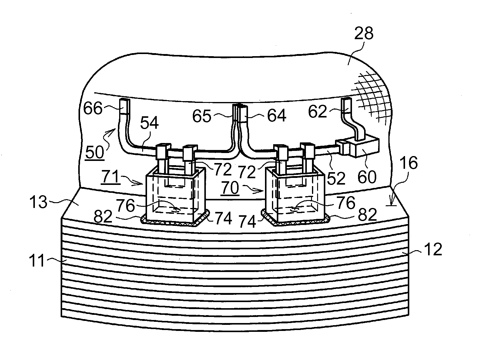
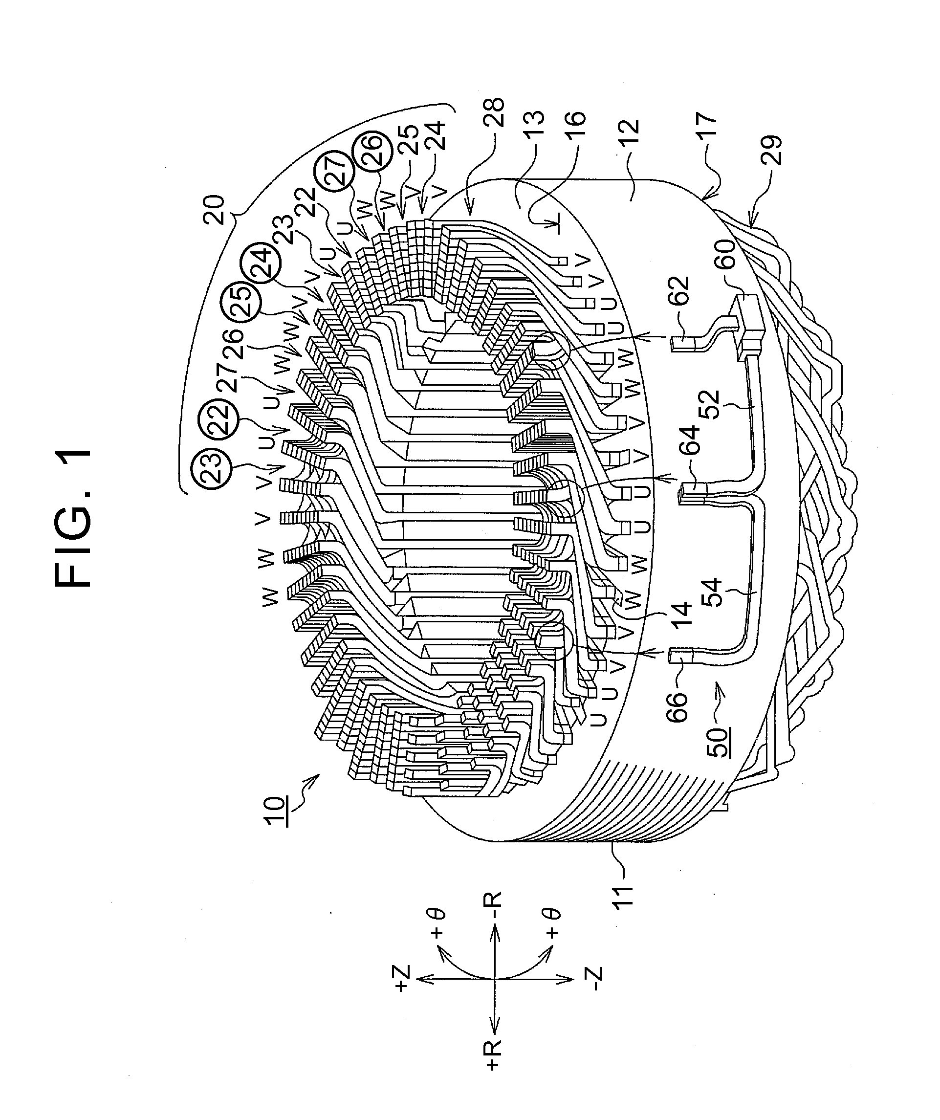
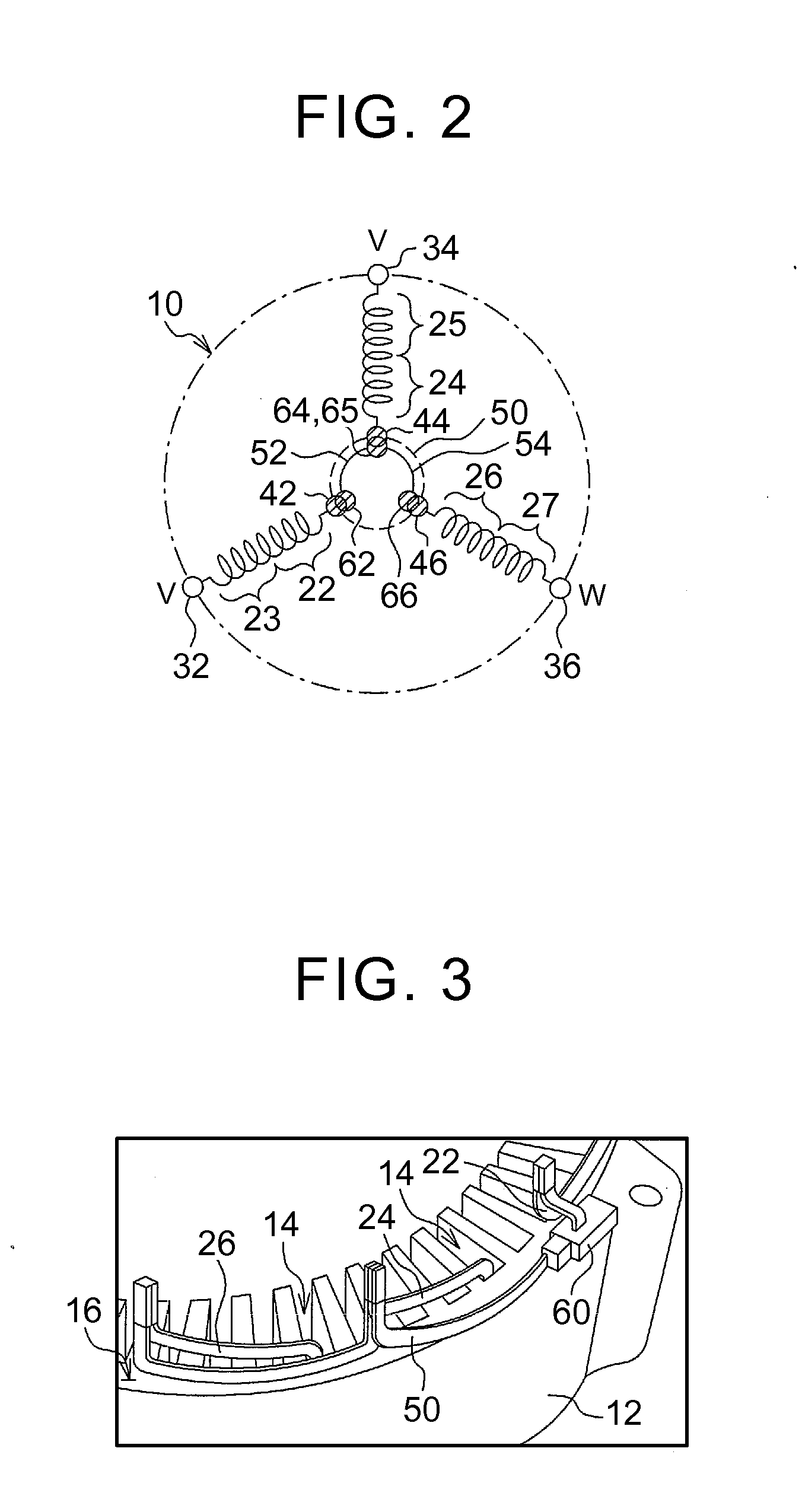
[0032]Example embodiments of the invention will hereinafter be described in detail with reference to the accompanying drawings. In the description below, the winding method of phase windings is a distributed winding method, the phase windings are formed by a plurality of conductor segments, and the conductor segments are made using flat wire with an insulation coating. However, this is merely an example for descriptive purposes. Another structure may also be used as long as it is a structure in which the phase windings are wound around a stator core, and one end of each phase winding is pulled out in order to be connected to a neutral line. For example, the structure may also be such that a winding having a circular cross-section or an elliptical cross-section is wound around a stator core.

[0033]The dimensions, shapes, and materials and the like described below are for descriptive purposes only, and may be changed as appropriate according to the specifications of the stator for the ...


PUM


Abstract

The stator includes a stator core, a plurality of phase windings, a neutral line and a fixing member. The plurality of phase windings are wounded a plurality of times by a predetermined winding method crossing between a plurality of slots. One lead end of each phase winding is supplied with a phase current. The other lead end of each phase winding is a neutral point connecting portion. The other lead end is pulled out from an axially end portion of the stator core. The neutral line connects the neutral point connecting portions of the phase windings of different phases together. The neutral line is separate from the phase windings. The fixing member fixes the neutral line to a yoke portion via an intermediate member. The intermediate member is made of resin.

Description

INCORPORATION BY REFERENCE[0001]The disclosure of Japanese Patent Application No. 2014-135600 filed on Jul. 1, 2014 including the specification, drawings and abstract is incorporated herein by reference in its entirety.BACKGROUND OF THE INVENTION[0002]1. Field of the Invention[0003]The invention relates to a stator for a rotary electric machine, and more particularly, to a stator for a rotary electric machine, in which ends of phase windings are connected at a neutral point (i.e., one end of one phase winding is connected to one end of another phase winding at a neutral point).[0004]2. Description of Related Art[0005]In a stator of a three-phase rotary electric machine, phase windings are wound by a predetermined winding method. A Δ connection and a Y connection are known methods to connect phase windings together. With a Y connection, ends of phase windings are connected at a neutral point (i.e., one end of one phase winding is connected to one end of another phase winding at a neu...

Claims


Application Information

Patent Timeline
IPC IPC(8): H02K3/28H02K3/38
CPCH02K3/28H02K3/38H02K3/50
Inventor KANESHIGE, KEIICHIMATSUMOTO, MASASHISHISHIDO, KUNIYOSHIWATANABE, ATSUSHISAKATA, YUJIIWAMOTO, HIROTSUGUMARUYAMA, TETSUYA
Owner TOYOTA JIDOSHA KK
Why Eureka
Try Eureka