Viscous rotational speed control device

a technology of rotating speed control and viscous, which is applied in the direction of watering devices, mechanical equipment, horticulture, etc., can solve the problems of excessive seal friction, water intrusion and/or excessive wear, and seal wear excess friction

Active Publication Date: 2016-07-14
NELSON IRRIGATION
View PDF8 Cites 12 Cited by
  • Summary
  • Abstract
  • Description
  • Claims
  • Application Information

AI Technical Summary

Benefits of technology

[0007]When the rotational speed of the input shaft changes due to changing pressures or nozzle size of the sprinkler, the rotor moves to a new axial position. The rotor is designed to cooperate with the housing or other nonrotating features within the housing to vary the shear gap in response to the axial position of the rotor. The rotor, housing and spring mechanism can be designed to cooperate to create large changes in braking torque in response to small changes in rotational speed of the input shaft. This allows the sprinkler or deflector plate rotation speed to be controlled within a relatively narrow range.

Problems solved by technology

Axial movement can drag water and other contaminants into the seal and thereby cause water intrusion and / or excessive wear.
Additionally, as the shaft moves into the housing, it pressurizes the fluid chamber, which can cause excess seal friction and seal wear unless an expansion chamber is added.

Method used


Image

  • Viscous rotational speed control device
  • Viscous rotational speed control device
  • Viscous rotational speed control device

Examples


Embodiment Construction

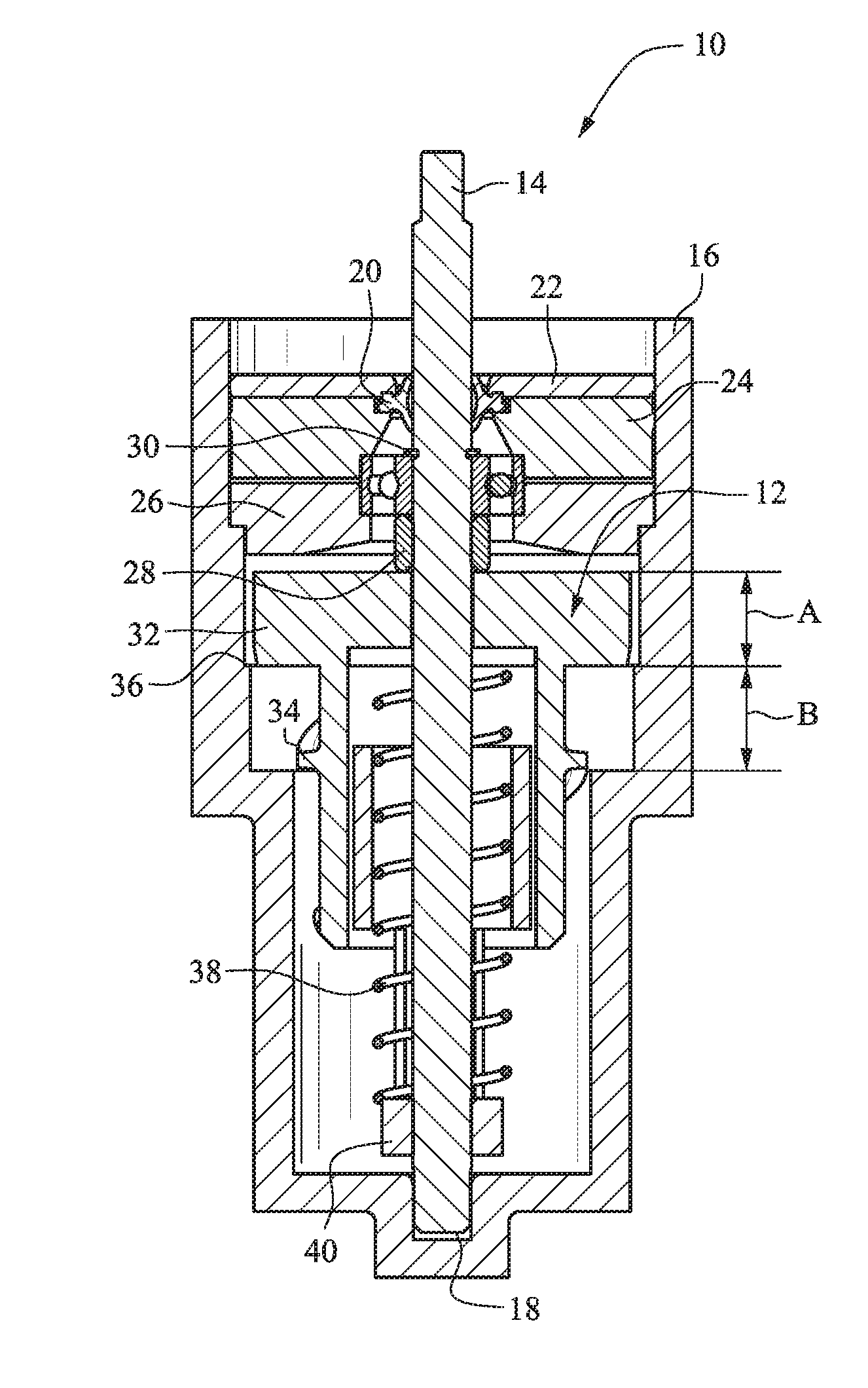
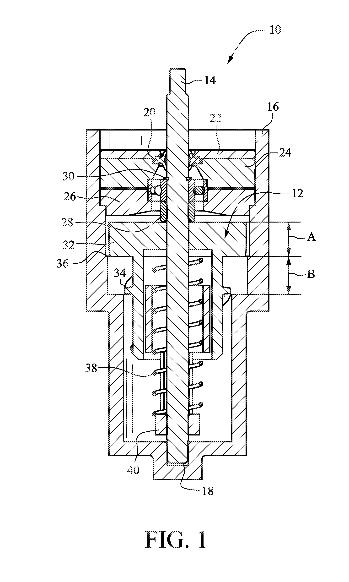
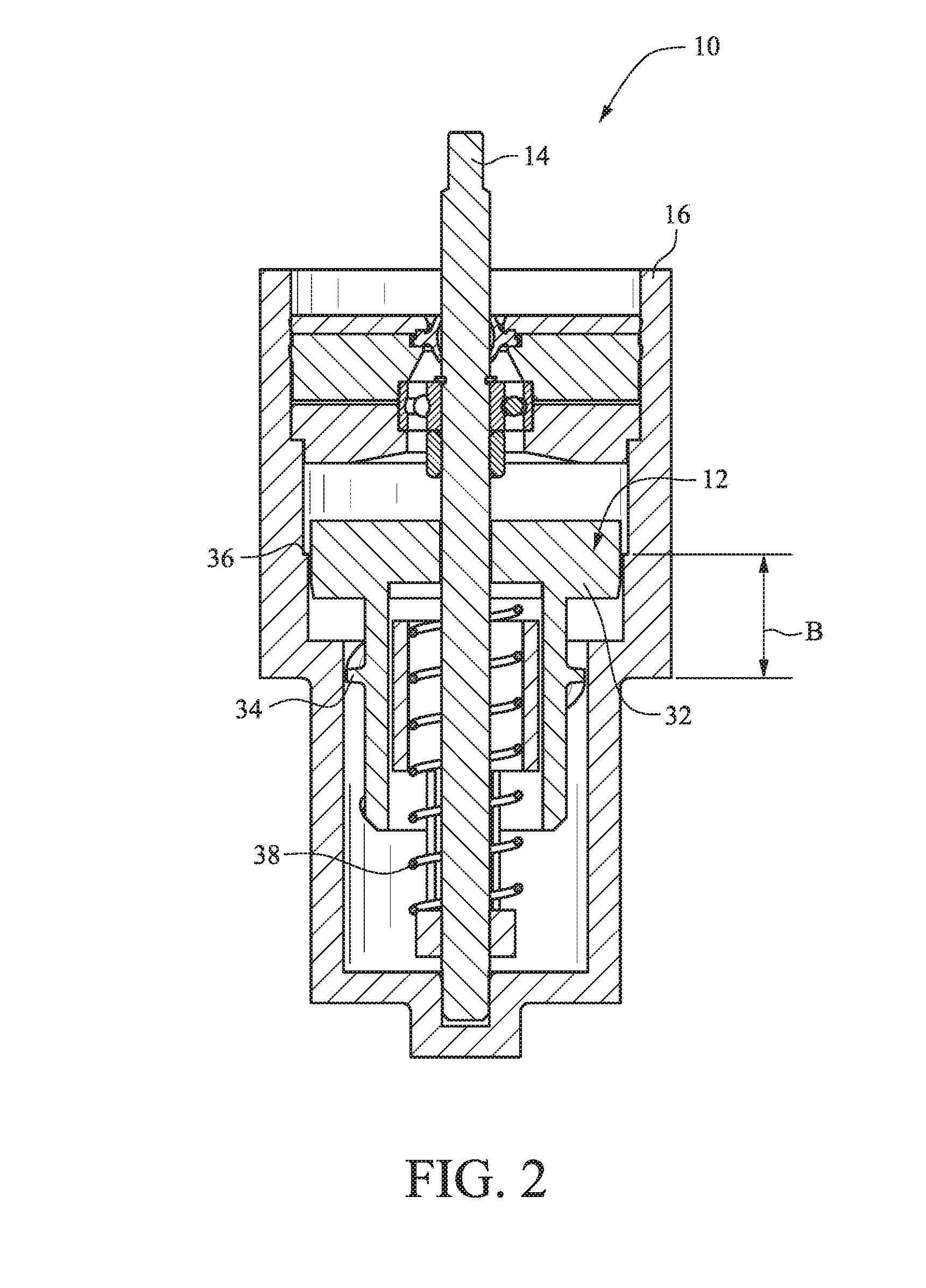
[0051]The figures show several embodiments of a viscous rotational speed control device 10. With reference to FIG. 1, a rotor 12 is rotatable with a shaft 14 in a housing 16. The deflector plate 15 is secured to the shaft 14 for rotation with the shaft 14. (See, e.g., FIG. 15.) The housing 16 is filled with a viscous fluid such as high-viscosity silicone fluid or the like. The housing 16 is closed at a bottom end and includes a recess or channel 18 for receiving the shaft 14. A seal 20 secured with a seal retainer 22 contains the viscous fluid within the housing 16.

[0052]A retaining ring 30 and a bearing retainer 28 are used to axially locate the ball bearing on the shaft 14. A lower bearing support 26 and an upper bearing support 24 cooperate to axially and radially locate the shaft bearing assembly in the housing 16. FIGS. 1-10 and 13 utilize a ball bearing to support the axial and radial load that the water imparts on the shaft 14. The axial load is transmitted to the housing 16 ...


PUM


Abstract

A rotational speed control device includes a housing containing a viscous fluid, a shaft disposed in the housing and rotatable relative to the housing, a hub assembly secured to the shaft for rotation with the shaft, and a rotor coupled with the shaft by a frictional engagement with the hub assembly. A spring is disposed in the housing and acts on the rotor to bias the rotor axially on the shaft in a low torque direction. A braking torque between the rotor and the housing is varied according to an axial position of the rotor on the shaft.

Description

CROSS-REFERENCES TO RELATED APPLICATIONS[0001]This application claims the benefit of U.S. Provisional Patent Application Ser. No. 62 / 103,168, filed Jan. 14, 2015, and is a continuation-in-part (CIP) of U.S. patent application Ser. No. 14 / 789,415 filed Jul. 1, 2015, and is a continuation-in-part (CIP) of U.S. patent application Ser. No. 14 / 699,445 filed Apr. 29, 2015, the entire content of each of which is herein incorporated by reference.STATEMENT REGARDING FEDERALLY SPONSORED RESEARCH OR DEVELOPMENT[0002](NOT APPLICABLE)BACKGROUND OF THE INVENTION[0003]It is desirable to maintain a relatively constant speed of rotation of an irrigation sprinkler regardless of nozzle size or pressure (i.e., mass flow rate and fluid velocity). This invention results in a large increase in braking torque for a small increase in rotational speed and therefore minimizes the change in rotational speed of the irrigation sprinkler when nozzle size or pressure is changed.[0004]For many years, a braking syst...

Claims


Application Information

Patent Timeline
Patent Type & Authority Applications(United States)
IPC IPC(8): F16D57/02F16D57/00
CPCF16D57/007F16D57/02A01G25/092B05B3/0486B05B3/005B60T10/02B05B15/70F16D57/00
Inventor SESSER, GEORGE L.PERKINS, LEE A.NELSON, CRAIG B.GREENWOOD, RILEY D.
Owner NELSON IRRIGATION
Why Eureka
Try Eureka